Figure 3-8 terminal lug, Ph 3-7, Ph 3-7) – Gasboy Fuel Truck Controller User Manual
Page 52
Fuel Truck Controller Manual
46
3
3
-
-
7
7
.
.
W
W
I
I
R
R
I
I
N
N
G
G
3
3
-
-
7
7
.
.
1
1
.
.
G
G
e
e
n
n
e
e
r
r
a
a
l
l
After completing the installation procedure, perform the wiring procedures. The wiring is
performed in the Fuel Truck Controller Terminal Block only.
The wires should be pulled from the conduits, or in the opposite direction, from the Terminal Block
to the devices in the fuel truck. Proceed as follows:
1. In accordance with the mapping, run cable conduits in accordance with the type of cables to
the spot:
One conduit from the pump valve
One conduit from the pulser
One conduit from the nozzle
One conduit from power
2. Run the cables along the conduits to the openings in the box. Connect the wiring through
optional glands or appropriate metal tubing. For UL/cUL listing, this product has only been
evaluated for use without the optional glands
3. Insert all power and communication cables pass through the openings in the bottom panel.
3
3
-
-
7
7
.
.
2
2
.
.
W
W
i
i
r
r
i
i
n
n
g
g
R
R
e
e
q
q
u
u
i
i
r
r
e
e
m
m
e
e
n
n
t
t
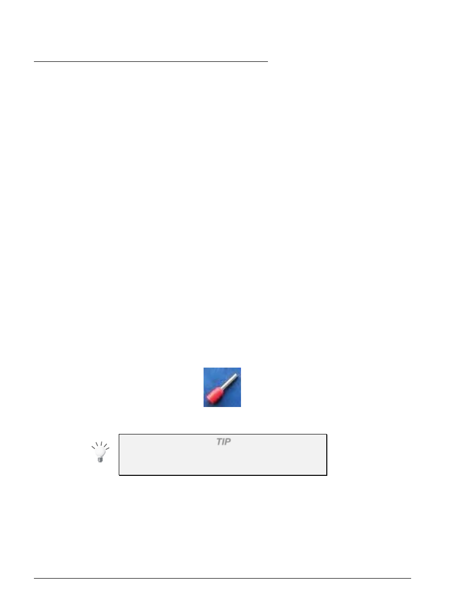
For any type of pump and wire, prior to inserting a wire, proceed as follows:
1. Insert all wires with a terminal lug only.
2. Use the proper Terminal Crimper to attach the lug to the wire.
3. For UL Listing, The Terminal Lug must be a UL recognized components.
Figure 3-8 Terminal Lug
TIP
Mark each cable at its both ends with a number or
sign that will identify its functionality in the future.
3
3
-
-
7
7
.
.
3
3
.
.
W
W
i
i
r
r
i
i
n
n
g
g
P
P
r
r
o
o
c
c
e
e
d
d
u
u
r
r
e
e
s
s
3
3
-
-
7
7
.
.
4
4
.
.
G
G
e
e
n
n
e
e
r
r
a
a
l
l
The wiring for Fuel Truck Controller is provided in two modes: