S in figure 3-2 – Gasboy Fuel Truck Controller User Manual
Page 48
Fuel Truck Controller Manual
42
3
3
-
-
5
5
.
.
5
5
.
.
S
S
h
h
o
o
c
c
k
k
A
A
b
b
s
s
o
o
r
r
b
b
e
e
r
r
s
s
A
A
s
s
s
s
e
e
m
m
b
b
l
l
y
y
-
-
I
I
n
n
s
s
t
t
a
a
l
l
l
l
a
a
t
t
i
i
o
o
n
n
P
P
r
r
o
o
c
c
e
e
d
d
u
u
r
r
e
e
s
s
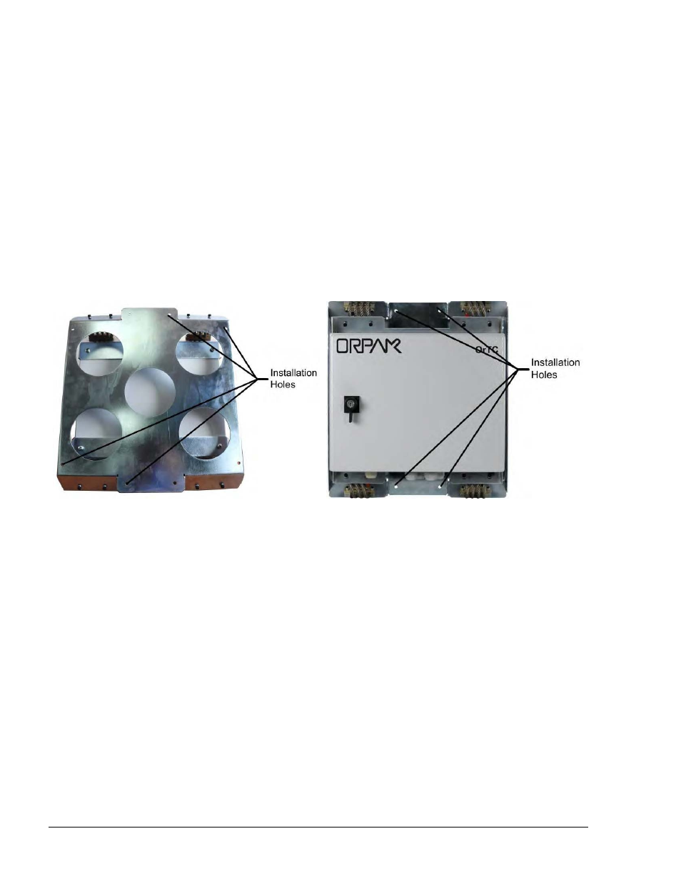
The Shock Absorbers Assembly should be mounted on any flat surface on the truck. The rear
wall of the shock absorber assembly includes eight holding holes for support screws.
Proceed as follows:
1. Locate the eight installation holes on the mounting flanges (see Figure 3-2 and Figure 3-3)
2. Check that eight M6 Hex threads in the installation flange have been drilled
3. Set Shock Absorbers assembly (2 in Table 3-1)on the spot (see Figure 3-2) so that its
installation holes fit with the threads
4. Secure Shock Absorbers assembly with eight M6 Pan head bolts, M6 flat washers and M6
spring washers (3, 4, 5 in Table 3-1)
Figure 3-2 Shock Absorber Assembly – Installation Holes
- 216S (18 pages)
- Atlas Fuel Systems Site Prep Manual (42 pages)
- Atlas Technician Programming Quick Ref (2 pages)
- ATC M05819K00X Kits (28 pages)
- Atlas Fuel Systems Owner Manual (80 pages)
- Gilbarco Global Pumping Unit Operation Manual (42 pages)
- 26 (7 pages)
- Atlas Valve Replacement Kits (10 pages)
- Atlas Fuel Systems Installation Manual (100 pages)
- 9120K (8 pages)
- 9820K (6 pages)
- Atlas Single Std. Inlet Centering Kit (8 pages)
- 8800 Atlas (1 page)
- 9120K Series Service Manual (40 pages)
- 9800A Atlas (6 pages)
- 9800 Atlas (14 pages)
- 9800 Atlas (20 pages)
- M08400 (6 pages)
- 9100 Series (8 pages)
- 9820K Series Installation (62 pages)
- 9853K (8 pages)
- 9216KTW (36 pages)
- Recommended Spare Atlas (14 pages)
- DEF Atlas (28 pages)
- 9820K Series (12 pages)
- 9800Q (1 page)
- Q Series (3 pages)
- 8753E (2 pages)
- 9152AXTW2 (1 page)
- 8800E (2 pages)
- 8800E (1 page)
- 9820Q Series (1 page)
- Atlas Start-up (230 pages)
- 9800Q Front Load Vapor (2 pages)
- 215A (1 page)
- 9800A (4 pages)
- 9820A (1 page)
- 2600A (3 pages)
- 2600A (12 pages)
- 2600A (2 pages)
- 216A (31 pages)
- 215A (2 pages)
- 9800Q Vapor (2 pages)
- Lamp Kit (2 pages)
- 9120Q Pulser (1 page)