3 hardware, Cabinet, Hardware – Gasboy Gilbarco Interface Unit User Manual
Page 35
Gilbarco Interface Unit v2.1
Hardware
27
Gasboy CFN Series
3
Hardware
This chapter is about the electrical parts of the interface. Ratings, jumper positions, and switch
settings are described in detail. The purpose of this chapter is to give specific detail in a
systematic fashion.
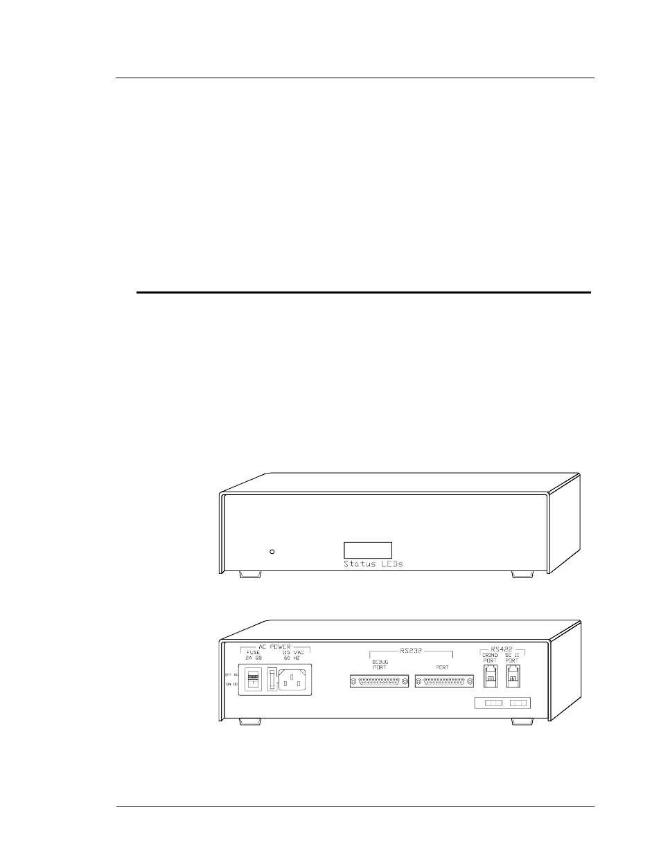
Cabinet
The interface unit cabinet is shown in figure below. The cabinet is three inches high, 12 inches
wide, and eight inches deep. It contains a power supply, the interface unit CPU board, and the
current loop driver board.
A short cable connects current loop driver board P1 to the upper two positions on a terminal
block, which provides for connection to the pump port on a distribution box (also called a D-
box).
The RS485/422 port on the right, shown in the figure with legend SC II Port above it,
provides for connection to the Site Controller.
The RS485/422 port on the left in the figure below, labeled CRIND PORT, provides for
connection to the CRIND port on a distribution box. A standard power entry module, labeled AC
POWER, provides for an instrument cord to supply power to the interface.
Front of Gilbarco Interface Unit
Back of Gilbarco Interface Unit
CURRENT LOOP
GSM