Service diagnostics, Cybex service manual – Cybex 525AT Arc Trainer User Manual
Page 22
22
23
Cybex Service Manual
Service Diagnostics
Service diagnostics allows testing, monitoring or altering of unit controls and performance.
1. Press the STOP key several times.
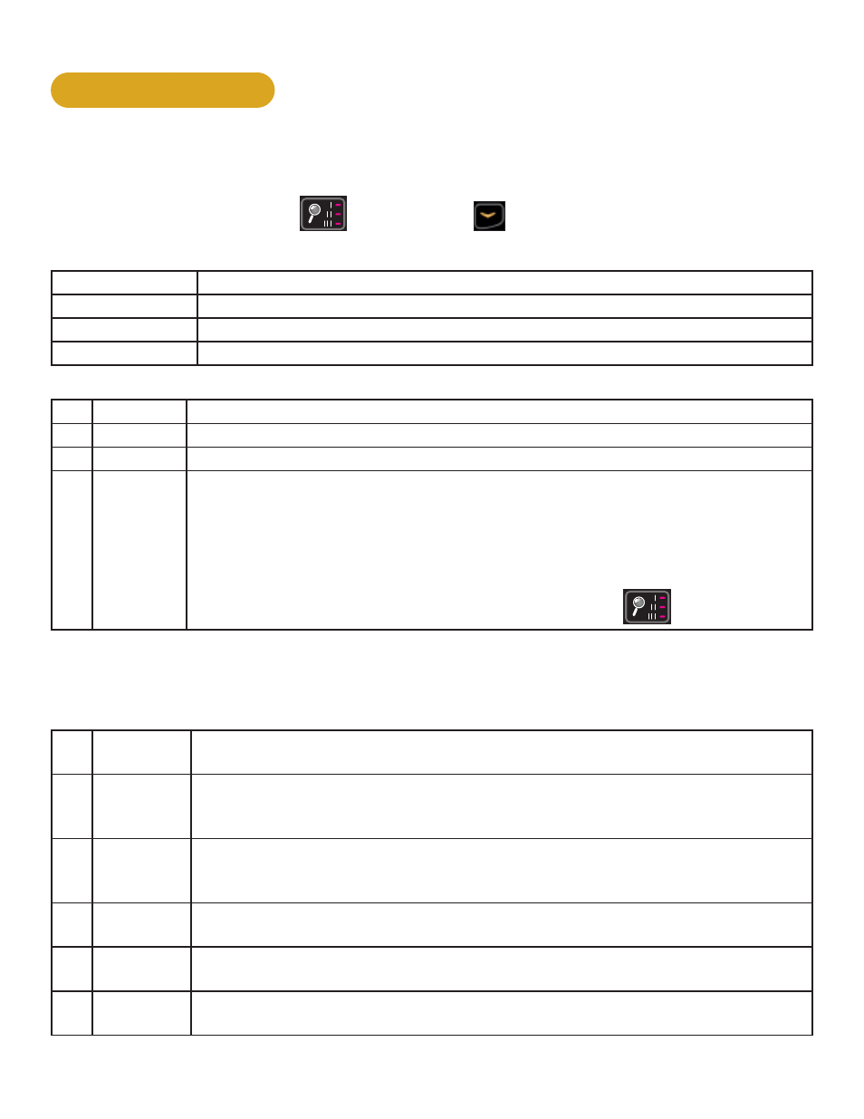
2. Press the Display option
MEMBRANE, HANDSET,
ARC, BIKE, TREADMILL,
ENGLISH
B
A
REVISIONS
DESCRIPTION
See sheet 1
ECO
REV
D A TE
APPRO V AL
BY
10 TROTTER DRIVE
MED W A Y , MA
RE V .
SHEET 7 OF 12
SIZE
APPRO V ALS
DR A WN BY
M A TERIAL
FINISH
ADOBE GENER A TED DR A WING
DO NO T MANUAL L Y UPD A TE
CHECKED
RES P ENG
MFG ENG
QUA L ENG
D A TE
DWG. NO.
UNLESS OTHE R WISE SPECIFIED
DIMENSIONS ARE IN INCHES
T OLERANCES ARE :
.XX ± .02
.XXX ± .010
ANGULAR = ± 1°
FINISH = 125 RMS
FRACTIONS = ± 1/64”
SCALE: 1=1
THIS FILE IS IN ADOBE ILLUSTR A T OR
DO NO T SCALE DR A WING
THE INFORM A TION CON T AINED IN THIS DR A WING IS THE SOLE PROPE R T Y OF CYBEX.
AN Y REPRODUCTION IN P A R T OR WHOLE WITHOUT
THE WRITTEN PERMISSION OF CYBEX IS PROHIBITED.
.
.
.
2/7/12
SW-23665-4
LIGHT GREEN PMS 354C (PT-3190)
DARK GREEN PMS 356C (PT-3515)
WHITE (PT-PE01)
YELLOW PMS 142C (PT-2325)
WINDOW DEAD FRONT (PT-3396)
BLACK (PT-PE02)
DARK GRAY PMS 425C (PT-3747)
RED PMS 185C (PT-892)
LIGHT GRAY PMS 424C (PT-2463)
DARK BLUE PMS 2925C
LIGHT BLUE PMS 2905C
RIM /PILLOW EMBOSSED AREAS
EMBOSS
GLOSS AREAS
key and
DOWN
key for three seconds.
Navigation while in Statistics or Diagnostic menus:
Up/Down keys
Scroll up and down in menu. Adjust data values.
Enter
Enter and exit menu items, move forward in menu if not required.
STOP
Exit back to Dormant Mode.
Quick Start
Select Diagnostics.
Statistics menu:
S1 Miles
Total distance in Miles or Kilometers.
S2 Hours
Total hours of workout time.
S3 Starts
Total number of workout starts.
S4 Error Log
Displays number of errors, up to 20. If no errors are stored “[ 0 ] [Err ] [Log]” will
be displayed.
To scroll through error log press
Enter, then use Up/Down keys.
When viewing error log use the
Enter key to toggle display to Time Stored, Date
stored, then back to error number.
Reset - While viewing error log press the
Display option
MEMBRANE, HANDSET,
ARC, BIKE, TREADMILL,
ENGLISH
B
A
REVISIONS
DESCRIPTION
See sheet 1
ECO
REV
D A TE
APPRO V AL
BY
10 TROTTER DRIVE
MED W A Y , MA
RE V .
SHEET 7 OF 12
SIZE
APPRO V ALS
DR A WN BY
M A TERIAL
FINISH
ADOBE GENER A TED DR A WING
DO NO T MANUAL L Y UPD A TE
CHECKED
RES P ENG
MFG ENG
QUA L ENG
D A TE
DWG. NO.
UNLESS OTHE R WISE SPECIFIED
DIMENSIONS ARE IN INCHES
T OLERANCES ARE :
.XX ± .02
.XXX ± .010
ANGULAR = ± 1°
FINISH = 125 RMS
FRACTIONS = ± 1/64”
SCALE: 1=1
THIS FILE IS IN ADOBE ILLUSTR A T OR
DO NO T SCALE DR A WING
THE INFORM A TION CON T AINED IN THIS DR A WING IS THE SOLE PROPE R T Y OF CYBEX.
AN Y REPRODUCTION IN P A R T OR WHOLE WITHOUT
THE WRITTEN PERMISSION OF CYBEX IS PROHIBITED.
.
.
.
2/7/12
SW-23665-4
LIGHT GREEN PMS 354C (PT-3190)
DARK GREEN PMS 356C (PT-3515)
WHITE (PT-PE01)
YELLOW PMS 142C (PT-2325)
WINDOW DEAD FRONT (PT-3396)
BLACK (PT-PE02)
DARK GRAY PMS 425C (PT-3747)
RED PMS 185C (PT-892)
LIGHT GRAY PMS 424C (PT-2463)
DARK BLUE PMS 2925C
LIGHT BLUE PMS 2905C
RIM /PILLOW EMBOSSED AREAS
EMBOSS
GLOSS AREAS
key twice.
Press the
Quick Start key to exit error log and enter Diagnostics menu.
Press the
Enter key to scroll through options.
Diagnostics menu:
T1 Test home Displays Drive software version, MCC board software version and heart rate
board version (POL - Polar or SAL - Salutron).
LED test
Press
Quick Start key to start. A quick LED text begins with lighting the following
for three seconds each. Bar Graph Matrix (BGM) LEDs and heart in red, center
numerics and heart in green, membrane LED’s and heart in blue.
Key test
Press
Workouts key to start. Test each key by pressing once. Each key press is
recognized with a beep, center numeric displays assigned number per key. Press
STOP key once to test, hold for two seconds to exit key test.
T2 Brake ID
Displays which brand of brake/generator is in use. Each one has different output
pulses. [PAR] - Paras brand, [C-H] - Chi Hua brand.
T3 Load
0 amps
Displays the load calibration value at 0 amps, no load.
T4 Load
1 amp
Displays the load calibration value at 1 amp.