Comtech EF Data PCB-4000 User Manual
Page 40
PCB-4000 1+1 Phase Combiner
Revision 2
Updating Firmware
MN/PCB4000.IOM
4–2
4.2
Getting Started: Preparing for the Firmware Download
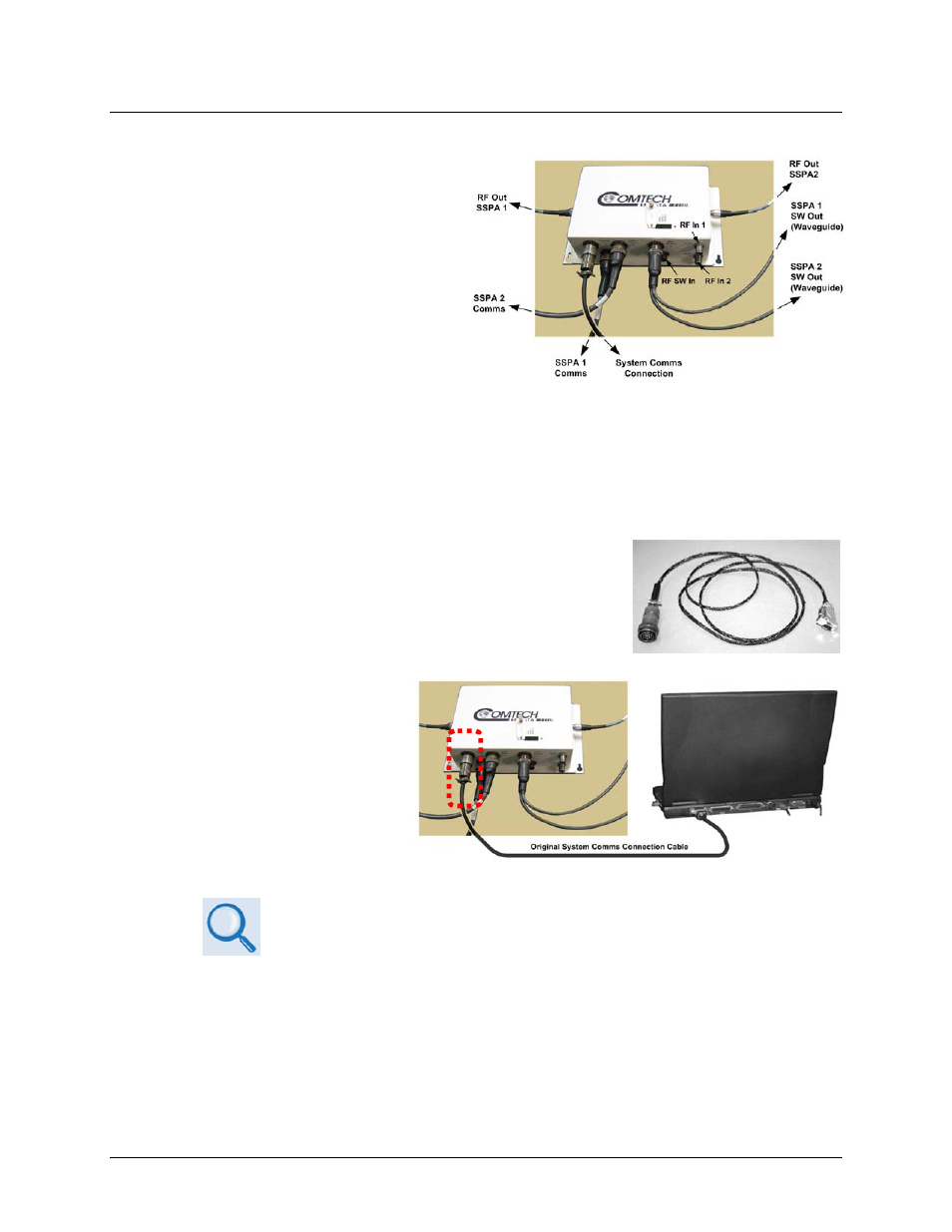
1. Locate and identify the PCB‐4000 1+1
Phase Combiner Control Box (PCCB).
The illustration at right identifies the
key cable connections between the
PCCB to the other components in and
a typical 1+1 Phase Combined System.
2. Connect the PCB‐4000 to a user‐supplied PC.
User‐supplied items needed:
• A Microsoft Windows‐based PC, equipped with an available serial port, and running a
terminal emulator program (e.g., Tera Term or HyperTerminal).
• A serial adapter cable for connecting the PC to the
PCB‐4000. If needed, the CA/ WR12243‐1 System
Programming Cable is available from Comtech EF
Data. Contact CEFD Customer Support for ordering
information.
A. Connect the user PC serial
port to the PCB‐4000
“SYSTEM COM | J1” port.
B. On the PC: Open the terminal emulator program.
Refer to your terminal emulator program HELP feature or user guide for
operating and configuration instructions.
Configure the utility program serial port communication and terminal display operation:
• 9600 or 19200 bps (Baud Rate)
• 8 Data Bits
• 1 Stop Bit
• Parity = NO
• Port Flow Control = NONE
• Display New line Rx/Tx: CR
• Local Echo = ON