3 “sspa out 2 | j10” connector, 4 power and ground interfaces, 1 ac power – Comtech EF Data PCB-4000 User Manual
Page 27: 2 ground connector
PCB-4000 1+1 Phase Combiner
Revision 2
External Connectors
MN/PCB4000.IOM
2–7
2.3.3
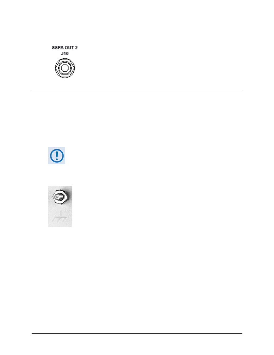
“SSPA OUT 2 | J10” Connector
The Type ‘N’ “SSPA OUT 2 | J10” connector, located on the right side panel of
the PCCB, provides the RF signal output from the PCCB to SSPA #2.
2.4
Power and Ground Interfaces
2.4.1
AC Power
The PCB‐4000 derives its power from the SSPAs. Each SSPA provides a +24V signal line via cables
interconnecting the SSPAs to the “SSPA COM 1 | J2” and “SSPA COM 2 | J3” connectors (Pin ‘R’
– see Table 2‐3 in Sect. 2.2.2). These two signals are “diode OR’ed” to provide redundancy.
Although the PCCB will turn on and function with only one SSPA powered on, the
system does not provide optimum output power unless both SSPAs are powered on.
2.4.2
Ground Connector
A #10‐32 stud is provided on the front panel of the PCCB for connecting a common
chassis ground among equipment.
- CDD-880 (124 pages)
- CDM-800 (130 pages)
- ODMR-840 (184 pages)
- CDM-750 (302 pages)
- CDM-840 (244 pages)
- SLM-5650A (420 pages)
- CTOG-250 (236 pages)
- CDM-700 (256 pages)
- CDM-760 (416 pages)
- CDM-710G (246 pages)
- CDM-600/600L (278 pages)
- CDMR-570L (512 pages)
- CDM-625 (684 pages)
- CDM-625A (756 pages)
- CDD-564A (240 pages)
- CDD-564L (254 pages)
- CLO-10 (134 pages)
- MCED-100 (96 pages)
- CDMR-570AL (618 pages)
- CDM-600 LDPC (2 pages)
- BUC Power Supply Ground Cable (2 pages)
- MPP70 Hardware Kit for CDM-570L (4 pages)
- MPP50 Hardware Kit for CDM-570L (4 pages)
- CDM-625 DC-AC Conversion (4 pages)
- CDM-625 DC-AC Conversion with IP Packet Processor (4 pages)
- DMDVR20 LBST Rev 1.1 (117 pages)
- DMD2050E (212 pages)
- DMD-2050 (342 pages)
- DMD1050 (188 pages)
- OM20 (220 pages)
- QAM256 (87 pages)
- DD240XR Rev Е (121 pages)
- MM200 ASI Field (5 pages)
- DM240-DVB (196 pages)
- MM200 (192 pages)
- CRS-150 (78 pages)
- CRS-280L (64 pages)
- CRS-170A (172 pages)
- CRS-180 (136 pages)
- SMS-301 (124 pages)
- CiM-25/8000 (186 pages)
- CiM-25 (26 pages)
- CRS-500 (218 pages)
- CRS-311 (196 pages)
- CIC-20 LVDS to HSSI (26 pages)