1 led status operation – Comtech EF Data PCB-4000 User Manual
Page 34
PCB-4000 1+1 Phase Combiner
Revision 2
Installation, Startup, and Troubleshooting Procedures
MN/PCB4000.IOM
3–6
3.3.1
LED Status Operation
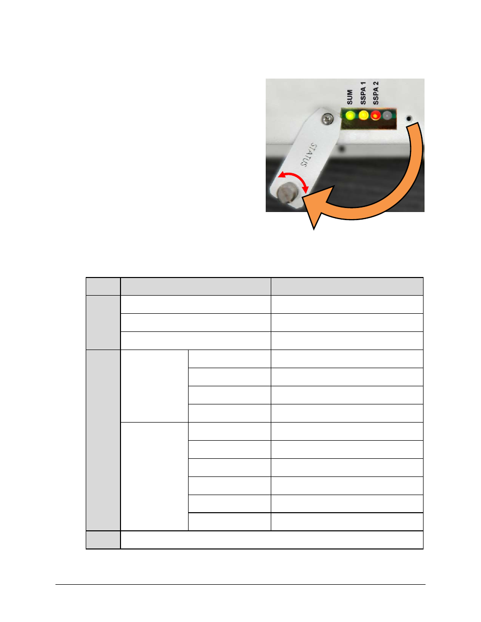
The PCB‐4000 1+1 Phase Combiner features four
Light‐Emitting Diode (LED) indicators – three are
operational, with the fourth reserved for future
applications. Each LED provides visual cues to the
operational, online, and offline status of the
system.
Figure 3‐4 illustrates the location of the LED
indicators. Located on the top of the PCB‐4000
enclosure under a pivoting protective plate, you
may view the LEDs by first loosening the captive
screw that keeps the plate in place, and then
swiveling the plate to reveal the LED display
window.
The behavior of the LEDs, as they appear under varying operational conditions, is as follows:
LED
Color / Behavior
Description
SUM
(LED 1)
Green
Phase Combiner has no summary fault.
Red (blinking)
A switch fault has occurred.
Red (constant)
A Summary Fault has occurred.
SSPA 1
(LED 2)
-or-
SSPA 2
(LED 3)
Phase-Combine
mode (RED=1)
Green (constant)
SSPA is unfaulted, unmuted and online.
Orange (constant)
SSPA is unfaulted but muted, and online.
Red (blinking)
SSPA is faulted and has gone offline.
Red (constant)
SSPA is faulted but online.
Non Phase-
Combine mode
(RED=0)
Green (constant)
SSPA is unfaulted, unmuted and online.
Green (blinking)
SSPA is unfaulted, unmuted and offline.
Orange (constant)
SSPA is unfaulted but muted, and online.
Orange (blinking)
SSPA is unfaulted but muted, and offline.
Red (constant
SSPA is faulted but online.
Red (blinking)
SSPA is faulted and has gone offline.
(LED 4)
Inoperable (always dark), reserved for future use
Figure 3-4. PCCB LED Display Window