Comtech EF Data RCF6001 User Manual
Page 69
RCF6001 Satellite Terminal
ODU Installation
TM082 - Rev. 1.0
Page 5-23
Mounting the Typical C-Band High Power Outdoor Unit Assembly
The following diagram and instructions pertain to mounting a 10-Watt, 20-Watt, 40-Watt or
60-Watt ODU (BUC) to an antenna using a Radyne ComStream supplied mounting plate and
hardware kits.
The Outdoor Unit is pre-assembled as shown in Figure 4-3. The User antenna type and design
determine the mounting location of this assembly. Refer to Table 4-4 for the mounting kit parts
list. The flexible waveguide is not provided with the mounting kit.
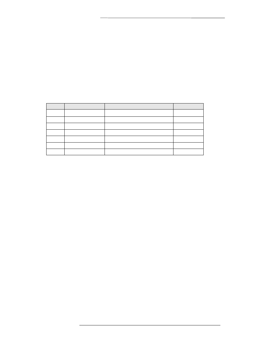
Table 4-9Offset Mounting Kit (3120-0002)
Item
Part #
Description
Qty
1
16267P2
Gasket
2
2
2400-3038-1008
SCRPNHD 10-32x5/8 LG
16
3
2400-3044-138
Washer, Medlock NO. 10
16
4
36015
U-Bolt
2
5
2400-3044-141
Washer, Medlock 3/8
4
6
2400-3045-814
Washer, FL 3/8 OD. 81
4
7
2400-3047-010
Nut, Plain Hex 3/8-16
4
Step 50. Important: Make sure that the Gasket is installed and that the waveguide flange is properly
sealed to prevent moisture from entering the waveguide.
Step 7. First secure the bottom section of the ODU mounting assembly by
placing the ODU (BUC) mounting assembly onto the diagonal support
member and secure using (1) U-Bolt and noted hardware.
Step 8. Secure the top section of the ODU (BUC) mounting assembly
onto the cross member (support pole/pipe) and secure using (1) U-Bolt and
noted hardware.
Step 9. If applicable, attach flexible waveguide between the ODU (BUC)
and feed assembly using the hardware noted.