Interface connections for the 5-watt ku-band – Comtech EF Data RCF6001 User Manual
Page 67
RCF6001 Satellite Terminal
ODU Installation
TM082 - Rev. 1.0
Page 5-21
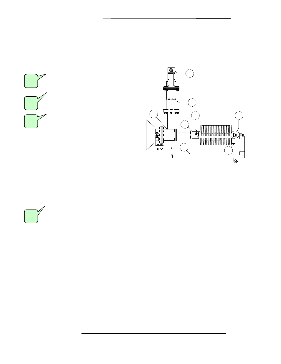
Interface Connections for the 5-Watt Ku-band
ODU
(
BUC
)
The following describes the various “USER” connections located on the 5-Watt C-band ODU
(BUC).
WR137 Waveguide Flange, Grooved
Function: ODU (BUC) RF Output port
CPR229Transmit Reject Filter (Optional)
Function: C-Band RF Connection to Reject
Filter
Male Type “F” Female Connector
Function: LNB Interface for L-Band Output
connection to IDU
6
2
4
5
7
8
3
1
Step 40. Provides +15 VDC source for LNB from IDU.
Step 41. Refer to Section 4.2, IFL Cable Installation Guidelines.
Step 42. Refer to Section 4.2.1, General Cable Installation Considerations prior to installing the cable.
Step 43. Refer to Table 4-2, IDU to ODU Interface Cable Requirements.
Female Type “N” Connector
Function:
ODU (BUC) Interface for L-Band Input connection from IDU
Step 44. Receives the modulated L-Band (950 - 1525 MHz) signal from IDU.
Step 45. Interface for a 10 MHz reference, 48 VDC power, and an FSK monitor and control (M&C) link.
Step 46. Refer to Section 4.2, IFL Cable Installation Guidelines.
Step 47. Refer to Section 4.2.1, General Cable Installation Considerations prior to installing the cable.
Step 48. Refer to Table 4-2, IDU to ODU Interface Cable Requirements.
4
1
2
3