Comtech EF Data RCF6001 User Manual
Page 18
Installation
RCF6001 Satellite Terminal
Page 2-6
TM082 - Rev. 1.0
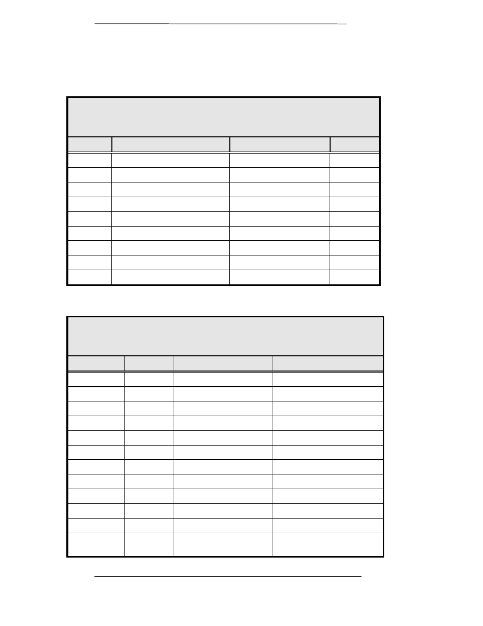
J4 - Remote
The RS-485 connection is for remote monitor and control of the modem.
Refer to Table 2-4 below for the pinouts.
Table 2-4.
J4- RS485 Remote Port - 9-Pin Female ‘D’
Pin No.
Signal
Description
Direction
1
RS485 TxD-B
Transmit Data B
Output
2
TxC-A
Transmit Clock A
Output
3
TxC-B
Transmit Clock B
Output
4
RxC-A
Receive Clock A
Input
5
Common
Signal Common
6
RS485 TxD-A
Transmit Data A
Output
7
RxC-B
Receive Clock B
Input
8
RS485 RxD-B
Receive Data B
Input
9
RS485 RxD-A
Receive Data A
Input
J9 – Data Interface
Table 2–5.
J9 - Sync Data RS422/RS485/RS232/V.35 - 37-Pin Female
Pin Number
Signal
Description
Direction
4
SD-A
Send Data A (-)
Input
22
SD-B
Send Data B (+)
Input
5
ST-A
Send Timing A (-)
Output
23
ST-B
Send Timing B (+)
Output
6
RD-A
Receive Data A (-)
Output
24
RD-B
Receive Data B (+)
Output
7
RS-A
Request to Send A (-)
Input
25
RS-B
Request to Send B (+)
Input
8
RT-A
Receive Timing A (-)
Output
26
RT-B
Receive Timing B (+)
Output
9
CS-A
Clear to Send A (-)
Output
14
MF
Mod Fault - Open
Collector
Output
- CDD-880 (124 pages)
- CDM-800 (130 pages)
- ODMR-840 (184 pages)
- CDM-750 (302 pages)
- CDM-840 (244 pages)
- SLM-5650A (420 pages)
- CTOG-250 (236 pages)
- CDM-700 (256 pages)
- CDM-760 (416 pages)
- CDM-710G (246 pages)
- CDM-600/600L (278 pages)
- CDMR-570L (512 pages)
- CDM-625 (684 pages)
- CDM-625A (756 pages)
- CDD-564A (240 pages)
- CDD-564L (254 pages)
- CLO-10 (134 pages)
- MCED-100 (96 pages)
- CDMR-570AL (618 pages)
- CDM-600 LDPC (2 pages)
- BUC Power Supply Ground Cable (2 pages)
- MPP70 Hardware Kit for CDM-570L (4 pages)
- MPP50 Hardware Kit for CDM-570L (4 pages)
- CDM-625 DC-AC Conversion (4 pages)
- CDM-625 DC-AC Conversion with IP Packet Processor (4 pages)
- DMDVR20 LBST Rev 1.1 (117 pages)
- DMD2050E (212 pages)
- DMD-2050 (342 pages)
- DMD1050 (188 pages)
- OM20 (220 pages)
- QAM256 (87 pages)
- DD240XR Rev Е (121 pages)
- MM200 ASI Field (5 pages)
- DM240-DVB (196 pages)
- MM200 (192 pages)
- CRS-150 (78 pages)
- CRS-280L (64 pages)
- CRS-170A (172 pages)
- CRS-180 (136 pages)
- SMS-301 (124 pages)
- CiM-25/8000 (186 pages)
- CiM-25 (26 pages)
- CRS-500 (218 pages)
- CRS-311 (196 pages)
- CIC-20 LVDS to HSSI (26 pages)