Comtech EF Data RCF6001 User Manual
Page 52
ODU Installation
RCF6001 Satellite Terminal
Page 5-6
TM082 - Rev. 1.0
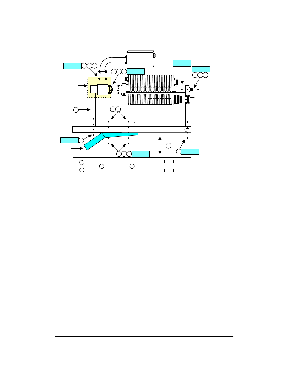
Figure 5-1.
ODU (BUC) Mounting Configuration
BUC4.VSD
LNB
1
2
7
8
8
Feed Support
5
6
6
4
10 11
9
13 14
12
13 14
12
Step 7
Step 2
Step 6
Step 3
Step 4
Step 5
Step 1
OMT is not provided
as part of the ODU.
This assembly is
provided by the user.
Step 1. Insert one “O” Ring (item 12) into the grooved flange of the ODU output
flange. Attach feed assembly (horn and OMT) to the output flange of the
BUC as shown in Figure 4-1, using four each #6 lock washers (item 14)
and 6-32x5/8 screws (item 13). Loosely insert all four screws then tighten
securely.
Step 8. Attach the horn support mount (item 1) to the mounting plate using two
1/4-20 flat head screws (item 8). Tighten screws securely.
Step 9. Attach the BUC rear support plate (item 2) to the mounting plate using two
1/4-20 flat head screws (item 8). Tighten screws securely.
Step 10. Place feed assembly and BUC on the mounting plate. The “neck” of the
horn should sit in the cradle of the horn support. Secure horn with top
strap and 1/4-20 bolts and lock washers (provided with antenna system).
Finger tighten bolts.
Step 11. Attach the BUC to the rear support plate using one each 3/8 flat washer
(item 11), 3/8 lock washer (item 10) and 3/8-16 bolt (item 9).