Comtech EF Data RCF6001 User Manual
Page 19
RCF6001 Satellite Terminal
Installation
TM082 - Rev. 1.0
Page 2-7
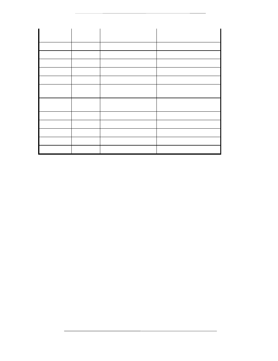
33
DF
Demod Fault - Open
Collector
Output
27
CS-B
Clear to Send B (+)
Output
11*
DM-A
Data Mode A (-)
Output
29*
DM-B
Data Mode B (+)
Output
13
RR-A
Receiver Ready A (-)
Output
31
RR-B
Receiver Ready B (+)
Output
3
BAL EXC-
A
External Clock A (-)
Input
21
BAL EXC-
B
External Clock B (+)
Input
16
RX-0-A
Receive Octet A (-)
Output
34
RX-0 B
Receive Octet B (+)
Output
17
TT-A
Terminal Timing A (-)
Input
35
TT-B
Terminal Timing B (+)
Input
1, 19, 20, 37
GND
Signal Ground
*NOTE: The DMD2401 Satellite Modem has the capability of constantly outputting the DM/DSR
signal. (DSR and DM are actually the same signal). The modem is always in the condition of
being able to pass data. DTR input to the modem is not necessary. The DM/DSR output of the
modem is located on pins 11 and 29 as shown above.
J6 – Ext. Ref. IN
This port is used for injecting an External Reference Frequency into the modem. The DMD2401
master oscillator is locked to this source. All internally generated frequencies within the modem
will attain the stability of the applied external reference. The external reference must meet the
following parameters:
Frequency:
256 KHz to 10 MHz in multiples of 8 KHz
Amplitude:
0.2 V p-p to 5 V p-p
Type:
Sinewave or Squarewave