2 g.703 connectors, 1 balanced g.703 (db-9f), 2 aux g.703 (db-9f) – Comtech EF Data CDM-625A User Manual
Page 93
CDM-625A Advanced Satellite Modem
MN-CDM625A
Rear Panel Connectors and Pinouts
Revision 3
3–9
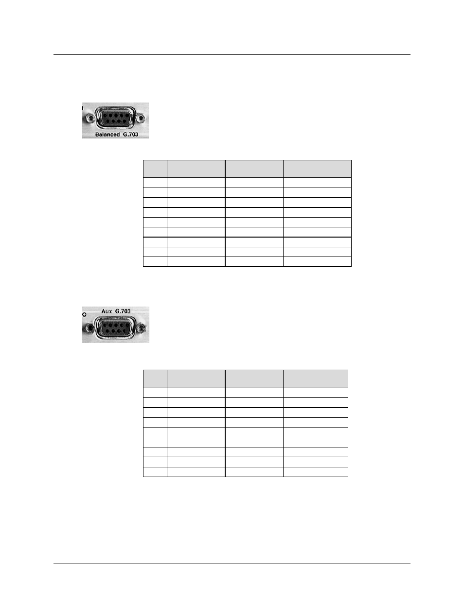
3.2.2.2 G.703 Connectors
3.2.2.2.1 Balanced G.703 (DB-9F)
The Balanced G.703 connector is a 9-pin Type ‘D’ female connector. It is
used for single port G.703, D&I or D&I++. When used with Quad E1
operations, this connector serves Ports 1 and 2 of the Quad E1 interface.
Table 3-3. Balanced G.703 Connector Pinouts
(R>L)
Pin #
Signal Function
Serial G.703
Signal Function
D&I or D&I++
Signal Function
Quad D&I
5
Tx in (+)
DDI (+)
Port 1 Tx In (+)
9
DDI (–)
Port 1 Tx In (–)
4
DDO (–)
Port 1 Rx Out (–)
8
DDO (+)
Port 1 Rx Out (+)
3
GND
GND
GND
7
IDI (+)
Port 2 Tx In (+)
2
IDI (–)
Port 2 Tx In (–)
6
Rx Out (+)
IDO (+)
Port 2 Rx Out (+)
1
Rx Out (–)
IDO (–)
Port 2 Rx Out (–)
3.2.2.2.2 Aux G.703 (DB-9F)
The Auxiliary G.703 connector is a 9-pin Type ‘D’ female connector. When
used with Quad E1 operations, this connector serves Ports 3 and 4 of the
Quad E1 interface.
Table 3-4. Auxiliary G.703 Connector Pinouts
(R>L)
Pin #
Signal Function
Serial G.703
Signal Function
D&I or D&I++
Signal Function
Quad D&I
5
–
–
Port 3 Tx in (+)
9
–
–
Port 3 Tx in (–)
4
–
–
Port 3 Rx Out (+)
8
–
–
Port 3 Rx Out (–)
3
–
–
GND
7
–
–
Port 4 Tx in (+)
2
–
–
Port 4 Tx in (–)
6
–
–
Port 4 Rx Out (+)
1
–
–
Port 4 Rx Out (–)