Comtech EF Data CDM-625A User Manual
Page 627

CDM-625A Advanced Satellite Modem
MN-CDM625A
Appendix F
Revision 3
F–21
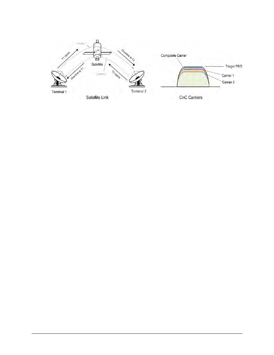
To recap, consider this diagram:
Whenever power is adjusted on Carrier 1, the power in Carrier 2 needs to be adjusted so the
composite carrier power remains constant (or does not exceed its allocated limit), while keeping
the CnC ratio within limits.
There are two distinct phases to the CnC-APC algorithm:
1)
In order for the CnC-APC algorithm to work effectively, it must first analyze the CnC Ratio
and Eb/No margins on each side of the link, and based on the starting conditions, re-
distribute power between the two ends so that good protection against fades can be
achieved. This process is referred as re-balancing, and is done so that total composite power
(TCP) in the two carriers remains constant (within ±0.5 dB).
In this process, both sides of the link calculate power changes, based on their ability to see
not only local parameters, including CnC Ratio, Eb/No, Receive signal level, power level and
max power increase, but those of the modem at the other end of the link. After these
calculations are performed, a comparison of the results is performed, and if they are in close
agreement, the power changes are implemented.
It may not always be possible to drive the powers to an optimum point. The calculations
take into account:
• The minimum and maximum power levels possible in the modem (as affected by the
selected operating band – 70/140 MHz IF versus L-Band).
• If the user-programmed value that determines the maximum permitted increase in Tx
power for the terminal would be exceeded. This is a very important value, and you
must know exactly how far from compression his transmit RF chain is operating. As an
example, if, under normal clear sky conditions, you determine that the backoff from
compression is -3 dB, and under no circumstances must the RF chain ever go past -1 dB,
the maximum power increase that can be permitted is 2 dB. You enter this into the
CDM-625A as a setup parameter. If this value is ignored, or incorrectly entered,
compression or saturation could occur, either during the initial re-balance, or during a
fade event. This parameter is referred to as TPLI
max
(Transmit Power Level Increase,
max).
