3 cdm-800 physical features, 1 front panel – Comtech EF Data CDM-800 User Manual
Page 25
CDM-800 Gateway Router
Revision 1
Introduction
MN-CDM800
1–5
1.3.3
CDM-800 Physical Features
1.3.3.1 Front Panel
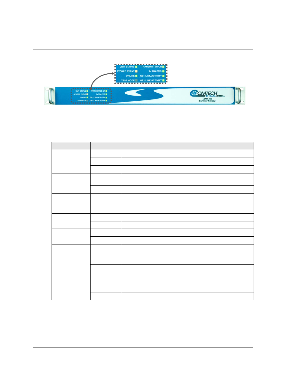
Figure 1-4. CDM-800 – Front Panel View
The front panel of the CDM‐800 (Figure 1‐4) features eight Light‐Emitting Diode (LED) indicators.
These LEDs convey operational states as follows:
LED
Condition
UNIT STATUS
Green
No Unit Faults or Alarms.
Amber
No Unit Faults, but an Alarm exists.
Red
A Unit Fault exists (Example: PSU fault).
STORED EVENT
Amber
There is a Stored Event in the log, which can be viewed from the Web
Server Interface or retrieved via the SNMP interface.
Off
There are no Stored Events.
ONLINE
Green
The Unit is On Line, and carrying traffic.
Off
The Unit is Off Line (standby – forced by externally connected 1:1 or
1:N Redundancy System).
TEST MODE
Amber
A Test Mode is selected (Example: CW).
Off
There is no Test Mode currently selected.
TRANSMITTER
ON
Green
The Transmitter Carrier is On.
Off
The Transmitter Carrier is Off.
Tx TRAFFIC
Green (solid)
No Tx Traffic Faults, no packets.
Green
(blinking)
No Tx Traffic Faults, blinks when a packet is being transmitted to the
satellite link from this unit.
Off
A Tx Traffic Fault exists.
GE1 or GE2
LINK/ACTIVITY
Green (solid)
Traffic Ethernet is connected, but no traffic exists.
Green
(blinking)
Ethernet activity detected.
Off
Traffic Ethernet is not connected.