Front panel diagnostic descriptions – Avery Dennison 676 User Manual
Page 66
66 •
••
• Appendix B
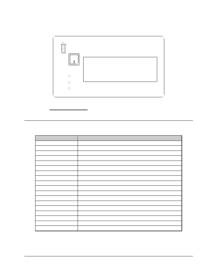
Front Panel Board P/N 351108
(Use chip removal tool p/n. 351156 for square I.C.'s)
FRONT PANEL BOARD, Upgradeable software I.C.'s include U1.
Align angled corners of chip with socket and arrow denotes pin #1 or dimple on chip.
Front Panel Diagnostic Descriptions
Diagnostic Numbers Descriptions
1
Front panel initialization
2
TCB Opsys initialization * See note below
5
Attempting Serial Host Initialization
6
Initializing Verifier
7
Executing Protected Mode Imaging Code
8
Checking Flash Disk Module
9
Attempting to read in scalable fonts.
10
Initializing Font Scaler
11
Attempting to load code pages
12
Attempting to read in logos
13
Attempting to read in care symbols
14
Waiting for Machine Definition from TCB
15
Attempting to create test pattern
16
Attempting to create strobe tables
17
Attempting to read in formats
18
Protected Mode Imaging Code initialization complete
19
Serial Communications Activated
0
Power up complete
Note: There must be a PCMCIA card installed in the slot if the PCMCIA option board is installed. If the
PCMCIA card is not present – the front panel will stop at Diagnostic 2.