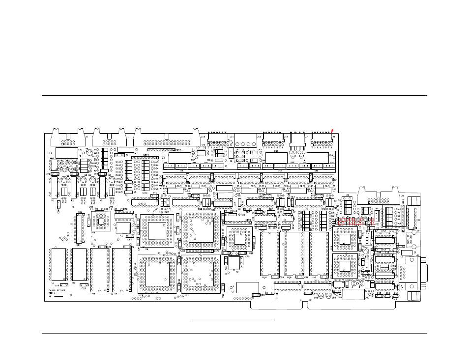
Appendix b, Software upgrade chip placement positions – Avery Dennison 676 User Manual
Page 64
This manual is related to the following products:
See also other documents in the category Avery Dennison Equipment:
- Monarch 1730 (4 pages)
- Pathfinder 6032 Supply (1 page)
- Pathfinder 6032 Quick Start (12 pages)
- Pathfinder 6032 Wrist Strap (4 pages)
- Platinum 6039 System Administrator Guide (48 pages)
- Platinum 6039 Weights and Measures (2 pages)
- Pathfinder 6140 Equipment Manual (36 pages)
- Pathfinder 6057 Quick Reference (40 pages)
- Pathfinder 6057 Quick Reference (115 pages)
- Pathfinder 6057 System Administrator Guide (60 pages)
- Pathfinder 6140 LNT Programmer Manual using XML (80 pages)
- Pathfinder 6140 Quick Reference (30 pages)
- FreshMarx 9415 Operator Handbook (44 pages)
- FreshMarx 9415 Maintenance Instructions (2 pages)
- FreshMarx 9415 System Administrator Guide (48 pages)
- Monarch 9416 XL Printer Equipment Manual (30 pages)
- Monarch 9416 XL Quick Reference (22 pages)
- FreshMarx 9415 Quick Reference (48 pages)
- Monarch 9416 XL AAFES Setup (4 pages)
- Monarch 9855 XL Intelligent Kit (34 pages)
- FreshMarx 9417 Replacing the Printhead (4 pages)
- FreshMarx 9417 Quick Reference (10 pages)
- Sierra Sport4 9493 Packet Reference Manual (230 pages)
- FreshMarx 9417 Operator Handbook (28 pages)
- Sierra Sport3 9433 Quick Reference (6 pages)
- FreshMarx 9417 System Administrator Guide (70 pages)
- 9450 RASCAL Programmer Manual (84 pages)
- Sierra Sport4 9493 System Administrator Guide (32 pages)
- Sierra Sport4 9493 Quick Reference (8 pages)
- Monarch 9855 RFMP Quick Reference (18 pages)
- 9850 Operator Handbook (134 pages)
- 7410 Network Card Programmer Manual (78 pages)
- Monarch 9855 MLI (4 pages)
- Monarch 9860 Quick Reference (12 pages)
- Monarch 9860 Operator Handbook (118 pages)
- Monarch 9860 Programmer Manual Addendum2 (14 pages)
- Monarch 9860 Programmer Manual Addendum (8 pages)
- Monarch 9864 Advanced Applications (21 pages)
- Monarch 9864 Quick Reference (28 pages)
- Monarch 9864 Error Messages (67 pages)
- Monarch 9864 Bar Code Information (19 pages)
- Monarch 9864 Command Overview (26 pages)
- Monarch 9878 (24 pages)
- Monarch 9864 Info Printouts and Parameters (111 pages)
- Monarch 9906 Quick Reference (48 pages)