Configuring remote control using rs-485, Caution: equipment damage – AMETEK XG Family Programmable DC User Manual
Page 139
Remote Operation
M370430-01 Rev E
5-7
5
Configuring Remote Control Using RS-485
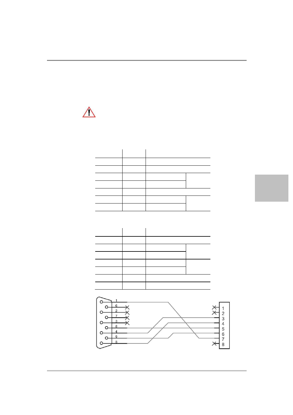
RS-485 Communication Cable with RJ-45 to DB-9
Communication control cable with DB-9 pinout (female) on the PC side
(see Figure 5-2) and RJ-45 shielded connector on the power supply.
CAUTION: Equipment damage
Figure 5-5 shows an example of wiring for NI RS485 communication
cable with DB-9. Refer to the user manual of your communication card
before wiring the cable.
Table 5-5 DB-9 Pinouts
Pin
Name
Description
1
GND
Ground
2, 3
NC
No connection
4
RXD+
Receive data
Twisted
pair
5
RXD-
Transmit data
6, 7
NC
No connection
8
TXD+
Transmit data
Twisted
pair
9
TXD-
Transmit data
Table 5-6 RJ-45 Plug Pinouts
Pin
Name
Description
1, 2
NC
No connection
3
TXD+
Transmit data
Twisted
pair
4
TXD-
Transmit data
5
RXD+
Receive data
Twisted
pair
6
RXD-
Receive data
7
GND
Ground
8
NC
No connection
DB-9 connector on PC
RJ-45 plug
Figure 5-5
RS-485 Communication Cable with DB-9
TXD+
RXD+
TXD–
RXD–
GND
TXD+
TXD–
RXD+
RXD–