6 remote monitoring – AMETEK DLM 600W Series User Manual
Page 73
DLM 600W Series
M362161-01 Rev J
4-15
4.5.2
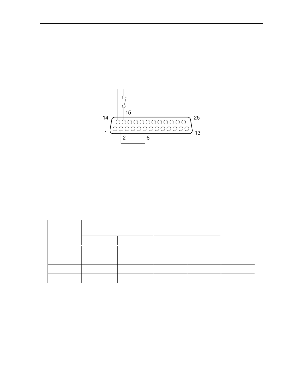
EXTERNAL–OFF with AUXILIARY 5 VDC OUTPUT
The internal AUXILIARY 5 VDC OUTPUT of the REMOTE ANALOG INTERFACE can
be used as the voltage source to drive the EXTERNAL OFF input. Because the 5 VDC
source is referenced to the other signals of the analog interface, opto–isolation would be
lost. The external contacts must then provide the isolation between the external control
circuits and the power supply. Refer to Figure 4-10 for connection information.
Figure 4-10. EXTERNAL–OFF with AUXILIARY 5 VDC OUTPUT
4.6 Remote Monitoring
Analog signals are available for monitoring the output voltage and current. These
signals vary proportionally to the output parameters, and have user selectable ranges of
0–5 VDC or 0–10 VDC for an output change from zero to full scale. Refer to
Table 4–4 for information on configuring the monitors.
Monitor
Signal
REMOTE ANALOG
INTERFACE Connections
SETUP Switch
Signal
Range
Signal Return
Position
Setting
Voltage
Pin-19
Pin-8
5, VMON
OFF
0–5 VDC
Voltage
Pin-19
Pin-8
5, VMON
ON
0–10 VDC
Current
Pin-7
Pin-8
4, IMON
OFF
0–5 VDC
Current
Pin-7
Pin-8
4, IMON
ON
0–10 VDC
Table 4–4. Remote Monitoring