AMETEK DLM 600W Series User Manual
Page 43
DLM 600W Series
M362161-01 Rev J
2-19
2.12.1 Parallel I/O Connector Pinout
The PARALLEL I/O connector is a 6–position connector, Molex #43045-0602. The
mating connector is Molex #43025-0600; and, its terminals are Molex #43030-0009.
The pinout is presented in Table 2–4.
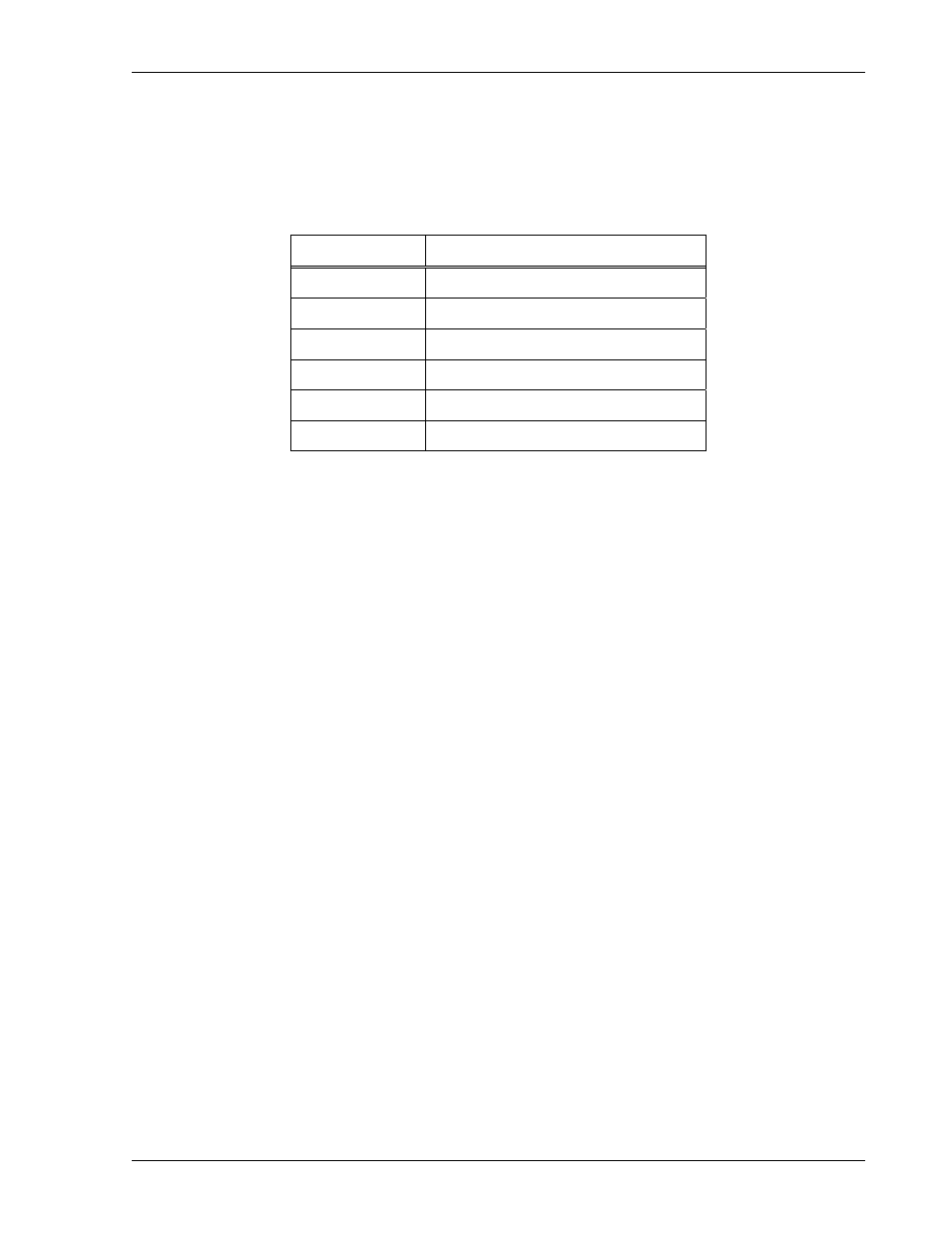
Pin Number
Function
1
Parallel Drive Bus
2
Parallel Drive Return
3
Parallel Disable Bus
4
Parallel Disable Return
5 Not
Used
6 Not
Used
Table 2–4. Parallel I/O Connector Pinout
2.12.2 Parallel I/O Interface Functions
The PARALLEL I/O INTERFACE provides control signals for implementing the
master/slave paralleling of multiple units. The following sections describe the functions
of the various signals. Pin numbers correspond to the PARALLEL I/O INTERFACE
connector pinout; also refer to Table 2–4.
PARALLEL DRIVE: Pin-1, output signal of a master unit and input signal of slave units
used for programming the slave units. Signal is not isolated from the negative (return)
output of the unit.
PARALLEL DRIVE RETURN: Pin-2, return for PARALLEL DRIVE signal. Signal is not
isolated from the negative (return) output of the unit.
PARALLEL DISABLE: Pin-3, active–low control signal common to both master and
slave units that will force all units to shut down if any one of the units shuts down.
Signal is not isolated from the negative (return) output of the unit.
PARALLEL DISABLE RETURN: Pin 4, return for PARALLEL DISABLE signal. Signal
is not isolated from the negative (return) output of the unit.
Unused Pins: Pin 5 and Pin 6.