AMETEK DLM 600W Series User Manual
Page 37
DLM 600W Series
M362161-01 Rev J
2-13
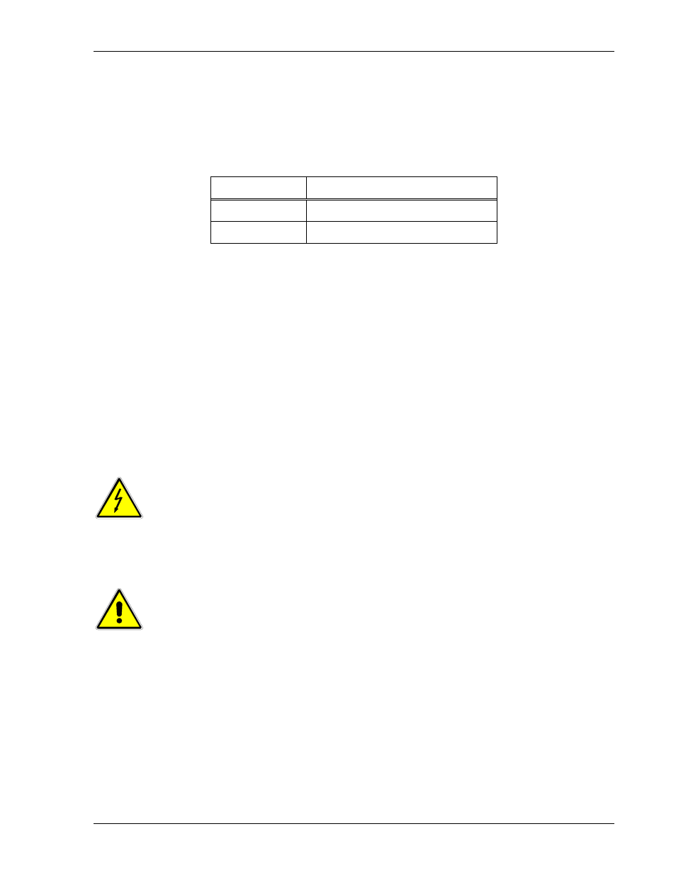
2.10.3 Remote Sense (REM SNS) Connector Pinout
The REMOTE SENSE (REM SNS) connector is a 2–position connector,
Molex #39-30-0023. The mating connector is Molex #39-01-3022; and its
terminals are Molex #39-00-0056. The pinout is presented in Table 2–3.
Pin Number
Function
1
Negative (–) Sense
2
Positive (+) Sense
Table 2–3. Remote Sense (REM SNS) Connector Pinout
2.11 Load Connection Configurations
The output of the DLM Series power supplies is isolated (see Note) from chassis
ground, allowing either positive, negative, or floating outputs with respect to chassis
ground. Connections to the load are made at the rear panel output terminals. Ensure
that a wire gauge is utilized that can carry the programmed current without overheating.
Either local or remote sensing of the output voltage is selectable, depending upon the
desired point of voltage regulation.
(Note: There is a I0M
resistor network connected from the output return(-) to the
chassis ground).
WARNING
The REMOTE ANALOG INTERFACE, REMOTE SENSE, and
PARALLEL I/O signals are connected to the negative (return) output
terminal. If the negative (return) output terminal is floated with respect to
chassis ground, those signals will also float at the same potential. Use
appropriate safety measures to prevent a shock hazard.
CAUTION
Operating the power supply with either the positive or negative
output lead floated greater than 300 VPK above chassis ground
could result in damage to the unit.
2.11.1 Connecting Single Loads
Single loads are connected directly to the rear panel output terminals. Twist the load
wires or maintain them closely in parallel for their entire length. Use the heaviest gauge
practical to minimize line drop. Figure 2-5 and Figure 2-6 show single load connections
with local and remote sensing, respectively.