AMETEK DLM 600W Series User Manual
Page 34
DLM 600W Series
M362161-01 K
2-10
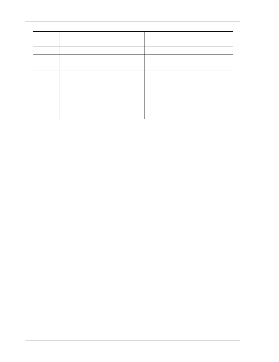
AWG
Copper Area,
cm
2
Resistance,
/m at 20°C
Resistance,
/m at 100°C
Current Rating,
A at 500A/cm
2
6 0.133 0.0013 0.0017 66.5
8 0.0837 0.0021 0.0028 41.9
10
0.0526 0.0033 0.0044 26.3
12
0.0331 0.0052 0.0069 16.6
14 0.0208 0.0083 0.011
10.4
16
0.0131 0.0132 0.0174
6.6
18 0.00823 0.0209 0.0276
4.1
20 0.00518 0.0333
0.044
2.6
22 0.00326 0.053
0.07
1.6
Table 2–2. Wire Data
2.9.2
Wire Voltage Drop
For applications where regulation is important, the contribution of the load wiring to
voltage drop from the power supply output terminals to the load must be considered.
The wire gauge must be selected to maintain an acceptable total voltage drop of the
load wiring under the maximum peak current. The resistance of the load wiring must be
determined for the sum total length of the positive lead and the negative lead.
Table 2–2 gives the resistance per meter (m) of various wire gauges at 20°C and
100°C. Use the following equation to calculate resistance for other wire temperatures:
R = R20°C
[1 + 0.004 (T-20°C)]
Where
R = resistance,
/m, at temperature T
R20°C = resistance,
/m, at 20°C
T = temperature, °C, of wire
The voltage drop (per positive or negative lead) can be calculated using the following
equation:
V = I
L R20°C [1 + 0.004 (T-20°C)]
Where
V = total voltage drop, V
I = load current, A
L = length, m, of load wire
R20°C = resistance,
/m, of wire at 20°C
T = temperature, °C, of wire conducting load current
The total voltage drop would be calculated by summing the drops of the positive and
negative leads.