AMETEK DLM 600W Series User Manual
Page 67
DLM 600W Series
M362161-01 Rev J
4-9
4.4.2
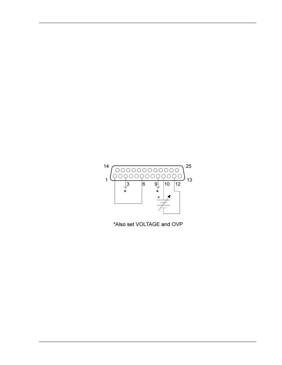
Voltage–Source Programming of Output Current
Refer to Figure 4-4 for setting up voltage–source programming of the output current.
1.
Set Position-7 of the SETUP switch to OFF for 0–5 VDC programming range.
2.
Set Position-7 of the SETUP switch to ON for 0–10 VDC programming range.
3.
Connect the external programming voltage source to the REMOTE ANALOG
INTERFACE connector, with positive to Pin-10 and negative to Pin-12.
4.
Program the other parameters to the desired limit values: VOLTAGE
PROGRAMMING INPUT, Pin-9, and the OVP PROGRAMMING INPUT, Pin-3,
with respect to Pin-12. AUXILIARY 5VDC OUTPUT, Pin-15, could be used for
full–scale programming.
NOTE: Step 4 is mandatory. The power supply will not work properly without it.
5.
Connect Pin-1, ANALOG–CONTROL, of the REMOTE ANALOG INTERFACE
connector to Pin-6.
Figure 4-4. Voltage–Source Programming of Output Current
- CW-M (48 pages)
- CW-M Corrected Table 4-2 in (1 page)
- CW-P (62 pages)
- Lx Series (205 pages)
- CW Series Programming Manual (25 pages)
- Ls Series II Programming Manual (242 pages)
- Compact i/iX Series (157 pages)
- Compact IX 2253 (157 pages)
- Compact i/iX Series Software Manual (203 pages)
- ASD Series Quick Start (5 pages)
- ASD Series (120 pages)
- i-iX Series II Programming Manual (226 pages)
- DLM 600W Series Programming Manual (24 pages)
- M131 Programming Manual (99 pages)
- DLM Series (74 pages)
- BPS Series (153 pages)
- DLM600 Series (16 pages)
- DCS-E 1.2kW Series (65 pages)
- DLM-E 4kW Series Programming Manual (32 pages)
- M136 (8 pages)
- DCS-E 3kW Series (94 pages)
- CTS 3.0 (166 pages)
- CSW Series (174 pages)
- 2003RP (126 pages)
- 2001RP (131 pages)
- MX CTSH (151 pages)
- MXCTSL Administrator Manual (27 pages)
- MX CTSL (157 pages)
- RS Series (228 pages)
- MX Series Installation Manual (35 pages)
- Ls AC source (2 pages)
- MX15 Series (184 pages)
- Ls Series II (226 pages)
- Lx Series Driver Manual (275 pages)
- MX Series Rev: AY (257 pages)
- iX Series (341 pages)
- i-iX Series II (258 pages)
- GUPS 2400A-108 (36 pages)
- HPD Series (58 pages)
- HPD Series Operation Manual (41 pages)
- HPD Series GPIB-Multichannel (134 pages)
- PLA-PLW Programming Manual (74 pages)
- ReFlex Mating Connnectors for Controller (3 pages)
- LPDC-16V (4 pages)