AMETEK DLM 600W Series User Manual
Page 65
DLM 600W Series
M362161-01 Rev J
4-7
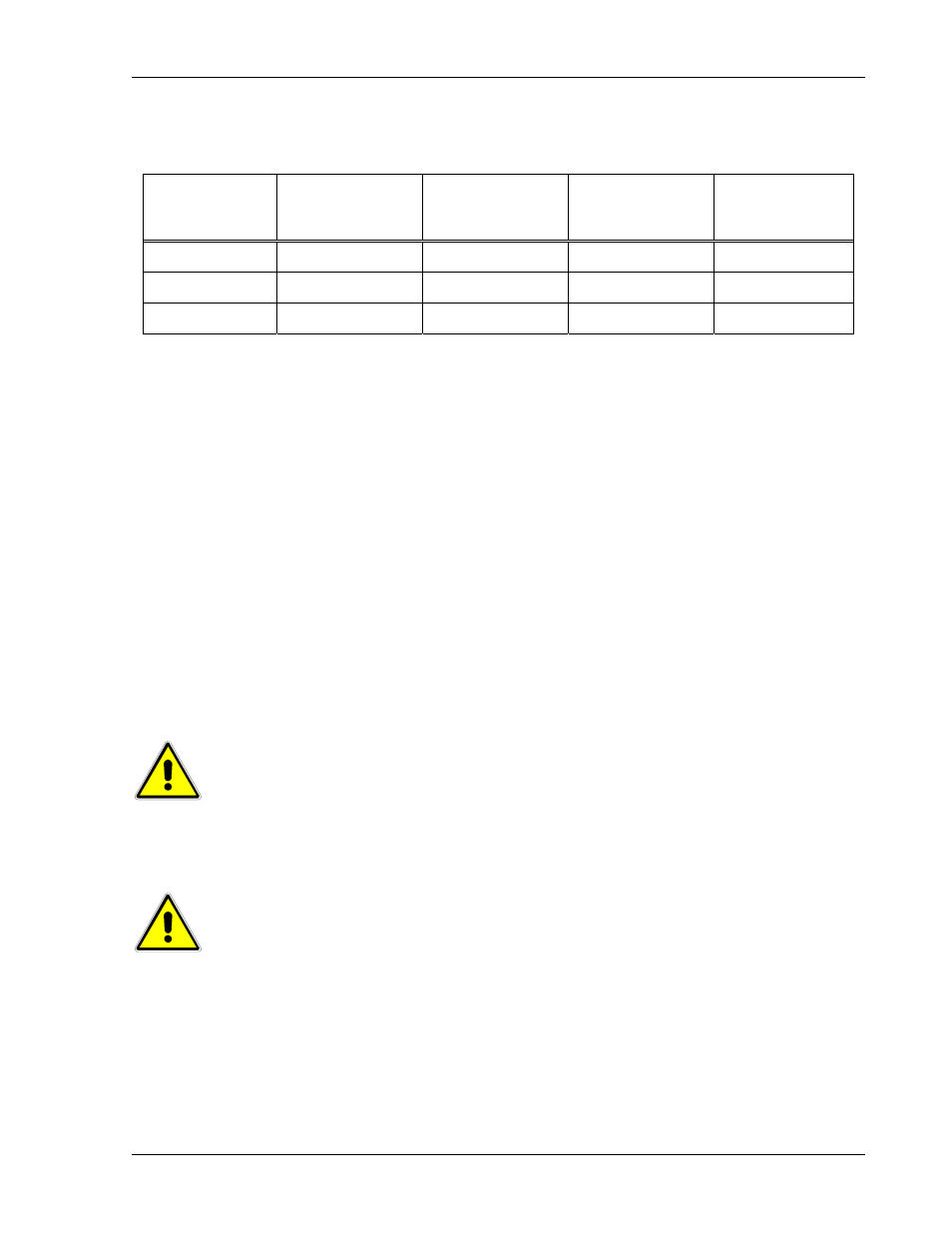
Table 4–3 presents the options for remote control operation; pin numbers refer to the
REMOTE ANALOG INTERFACE connector.
Mode of
Operation
Analog–Control
Signal, Pin-1
Local–Lockout
Signal, Pin-24
Power–Up
State
Local/Remote
Toggling
Remote Only
Low
Low
Remote
No
Local Only
Open
Open
Local
No
Local/Remote Low
Open
Remote
Yes
Table 4–3. Remote Programming Options
When remote programming is enabled, front panel control is disabled for all parameters.
Therefore, all three parameters must be set remotely: The parameters to be controlled
would be connected to the programming sources, while the others would be pulled up to
full scale or the desired limit. This can be accomplished with resistance programming of
the parameters that would not be adjusted, or by programming them to full scale with
the AUXILIARY 5V OUTPUT (the 0–5 VDC range must be selected).
Use appropriate measures to ensure that the wiring connected to the REMOTE
ANALOG INTERFACE connector is protected from noise coupling. Noise appearing on
the programming signals could modulate the output of the unit. Depending upon the
noise environment of the application, the wires may have to be twisted and shielded.
Also, if the output negative (return) is floated with respect to chassis, the signals of the
REMOTE ANALOG INTERFACE connector (except for the opto–isolated EXTERNAL–
OFF signal) will float at the same potential. Ensure that the interface circuitry can
withstand the float potential.
CAUTION
The signals of the REMOTE ANALOG INTERFACE connector have
internal connections to the output negative (return) terminal.
Damage could result if they are connected to the power supply
output positive.
CAUTION
Ensure that the unit is unplugged from the AC input prior to making
any changes to connections of the remote interface or settings of the
SETUP switch.