Vortech 2005-2008 Ford 4.0L V6 Mustang User Manual
Page 34
P/N: 4FU020-610
©2008 Vortech Engineering, LLC
All Rights Reserved, Intl. Copr. Secured
06AUG08 v4.1 05MusV6(4FU..610v4.1)
24
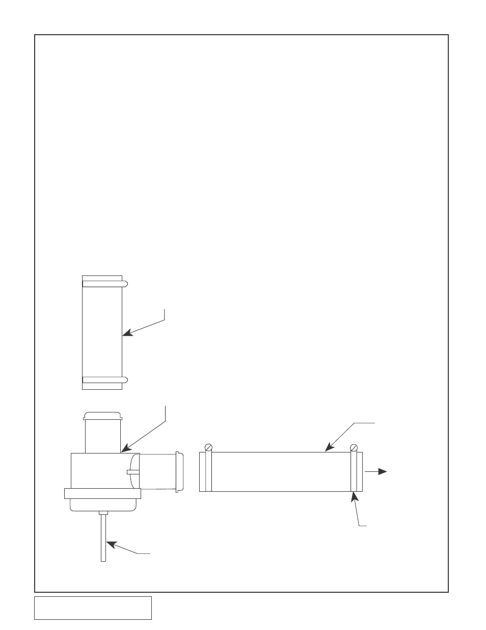
Fig. 7H-a
H. COMPRESSOR BYPASS VALVE
ASSEMBLY INSTALLATION
1. Assemble the bypass using a piece
of Ø1" hose cut to 6" long and a
piece cut to 24" long and four #16
hose clamps.. (See Fig 7H-a)
2. Attach the 6" piece of hose to the
inlet of the bypass and secure with
a clamp. (See Fig. 7H-a)
3. Secure the 24" piece to the outlet
of the valve, securing it with a
clamp. (See Fig. 7H-a.)
4. Attach the bypass assembly to the
charge cooler. The 6" long piece
will be attached to the charge cool-
er. Secure with clamps. Leave the
24" long section open for future
attachement to the air inlet.
5. Attach a length of 5/32" vacuum
hose to the bypass valve and route
to the vacuum port on top of the
intake manifold.
6. Remove the plastic union connect-
ing the fuel rail pressure sensor to
the intake manifold. Install the sup-
plied TEE in its place. (See Fig.
8-b.)
7. Attach the vacuum hose from the
bypass valve to the TEE.
Once Section 7 has been complet-
ed, skip Section 8 and proceed
with Section 9.
7. CHARGE AIR COOLER INSTALLATION (H.0. Kits Only), cont’d
6" x 1" HOSE
Ø
(TRIM TO FIT)
TO DISCHARGE
TUBE AT THE
THROTTLE BODY
24" x 1" HOSE
Ø
(TRIM TO FIT)
TO MANIFOLD PRESSURE/VACUUM
#16 HOSE CLAMPS
BYPASS
VALVE
TO INLET
DUCT