Vortech 2005-2008 Ford 4.0L V6 Mustang User Manual
Page 32
P/N: 4FU020-610
©2008 Vortech Engineering, LLC
All Rights Reserved, Intl. Copr. Secured
06AUG08 v4.1 05MusV6(4FU..610v4.1)
22
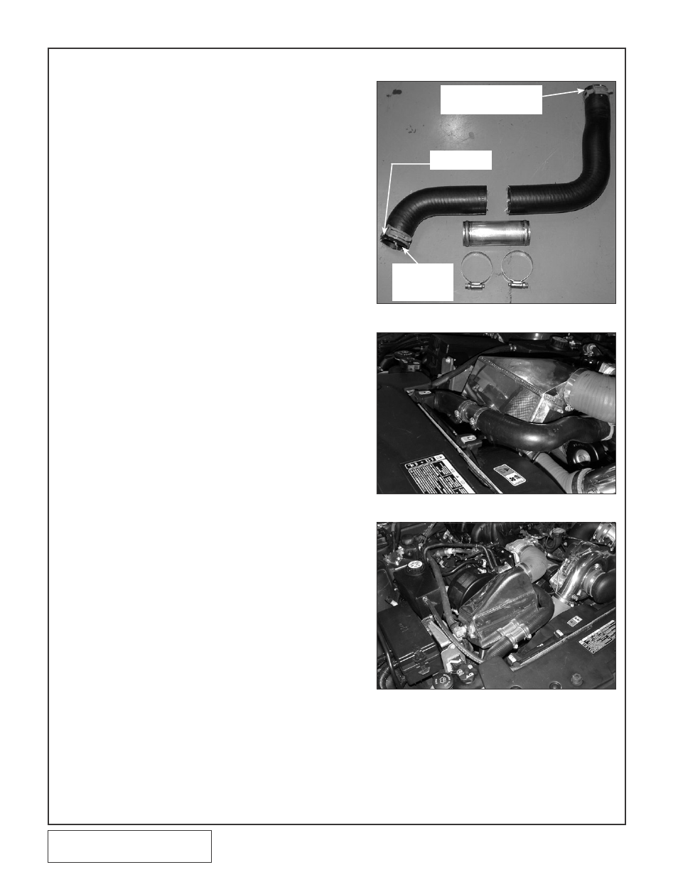
Fig. 7F-a
Fig. 7F-b
Fig. 7F-c
F. RADIATOR HOSE MODIFICATIONS
1. Remove the passenger’s side upper radi-
ator hose.
2. Modify the upper hose by cutting the
hose. (See Fig. 7F-a.)
3. Attach the hose to the stainless union
with a #24 SS hose clamps.
4. Trim the short 90° hose end that was
previously connected to the engine (it will
now be connected to the radiator) so as
to bring the hose as close to the radiator
as possible. Secure using the factory
hose clamp. (See Figs. 7F-a, 7F-c.)
5. Attach the open end of the hose assem-
bly to the engine and secure using the
factory hose clamp. Adjust the hose
assembly to allow as much room as pos-
sibly for cooler clearance in a following
step. Secure all clamps at this time.
(See Figs. 7F-b, 7F-c.)
6. Attach the long end of the 2.75" silicone
elbow to the cooler inlet and loosely
install a #44 hose clamp. The open end
of the elbow should be facing up as it will
be attached to the supercharger dis-
charge.
7. Lower the cooler assembly into position.
Attach the open end of the previously
installed 2.75" elbow to the supercharger
discharge and loosely install a #44 hose
clamp.
8. Attach the cooler discharge to the previ-
ously installed elbow.
9. Tighten all cooler clamps at this time.
10. Install a 1/2"NPT x 3/4" x 90° fitting in the
lower hole in the charge cooler end tank.
Tighten and leave pointing down.
11. Take the remaining “short” 1/2"NPT x
3/4" x 90° fitting (set aside in Step 7B-10)
and install it in the upper hole in the
charge air cooler end tank. Leave this fit-
ting pointed towards the rear of the vehi-
cle.
12. Attach a length of 3/4" hose from the 90°
fitting on the surge tank to the rear facing
fitting on the charge air cooler.
13. Attach a section of 3/4" hose to the fitting
on the charge air cooler that is pointing
down and route to the hose union previ-
ously installed in the 90° on the driver’s
side of the water cooler and secure all
hose connections with the nylon ratchet
clamps provided.
7. CHARGE AIR COOLER INSTALLATION (H.0. Kits Only), cont’d
TRIM THIS
END
PREVIOUSLY
CONNECTED
TO RADIATOR
PREVIOUSLY
CONNECTED
TO
THE ENGINE