StorCase Technology FC-to-SCSI Single & Dual RAID User Manual
Page 27
14
Installation
StorCase Technology, Inc.
FC-SCSI Dual RAID Module User's Guide - Rev. A01
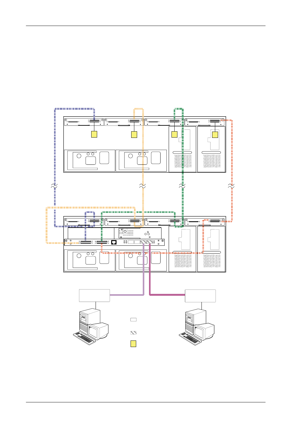
Figure 7B: Typical Stand-Alone Single RAID, Dual Loop Configuration
(Multiple 14-Bay Chassis with Single RAID Controller Module Unit Installed)
T
IFSII_FDR7
Disk Ch. 0
(4 Drives)
Disk Ch. 1
(3 Drives)
Disk Ch. 2
(4 Drives)
Disk Ch. 3
(3 Drives)
T
T
T
PC
FC HBA
Host 1
PC
FC HBA
Host 0
14-Bay InfoStation
(Single RAID Controller Module Installed)
14-Bay InfoStation JBOD
FC-AL #2
FC-AL #1
= No SFP
Module Installed
(Auto-Loopback)
T
= SCSI Terminator
= SFP Module
Installed
NOTES:
For stand-alone configurations, the Single RAID Controller Module should be installed in
the Controller A (Primary) location only.
For stand-alone configurations, only RAID Controller A Host ports should be used to con-
nect to FC Hosts 0 & 1. RAID Controller B Host ports are for loop expansion only.
Auto Loopback is enabled when there are no SFP Modules installed in the open Host ports.
Cover plate (provided) must be installed if module slot is left empty. Installation of
cover plate is necessary for proper cooling inside chassis.
Up to 15 disks per SCSI Channel with Single RAID Controller Module Unit installed.
(15 Disks x 4 Channels = 60 Disks Total)