Martin Christ RVC 2-33 CDplus User Manual
Page 25
RVC 2-33 CD
&
Set-up and Connection
Version 01/2009, Rev. 1.21 of 25/11/2013 - sb
25
Translation of the original operating manual
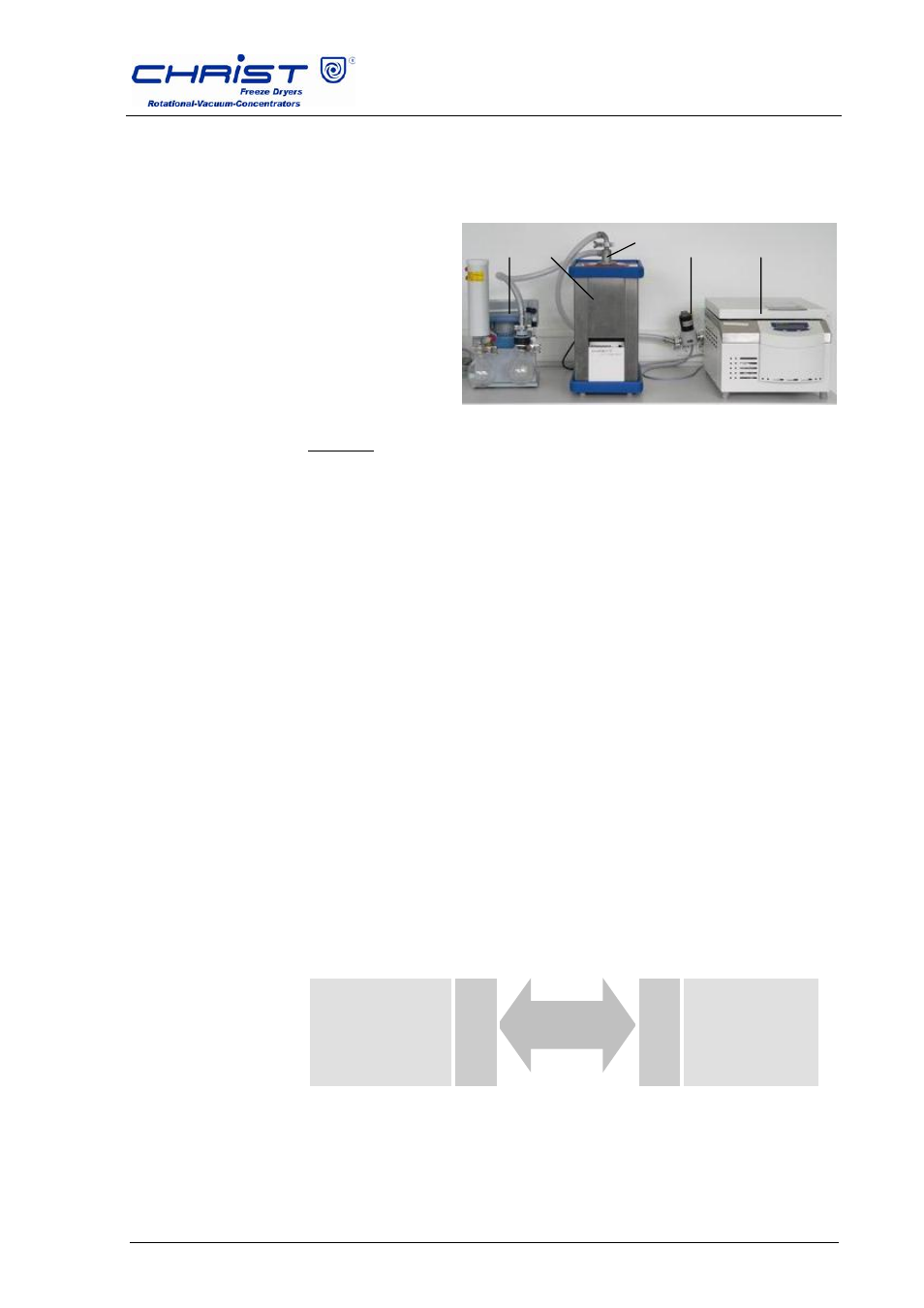
Condensation of the vapours upstream of the vacuum pump in a
cooling trap, e.g. CT 02-50 or CT 04-50 in connection with a vacuum
pump.
For water-based, low-boiling samples containing solvents
1 Vacuum pump
2 Cooling trap
3 Cover with hose
4 Stop valve
5
Rotational
vacuum
concentrator
Fig. 5.2: Connection of he vacuum pump and cooling trap
Attention: The set-up in the photo is for demonstration purposes only!
Normally, the stop valve is installed behind the rotational vacuum
concentrator and cannot be seen from the front.
The rotational vacuum concentrator, the cooling trap and the vacuum
pump must be connected. The connector of the stop valve must be
plugged into the socket on the back of the unit.
Option: Cooling trap control
If
christ
freeze dryers are used as a cooling trap, they can be
remote-controlled by the rotational vacuum concentrator. In this
case, the cooling trap will be automatically activated by the rotational
vacuum concentrator during the warm-up and evaporation phase. In
the standby mode, the cooling trap will be either switched off or
continue operation, depending on the choosen option (siehe 6.3.5.5
"Options / Settings / Continuous operation coldtrap"). The ice
condenser temperature is indicated in the values window of the
rotational vacuum concentrator.
The cooling trap must be connected to the rotational vacuum
concentrator with the aid of a zero cross cable (part no. 222000). In
addition, the option "Cooling trap control" must be activated (see
6.3.5.5 "Options").
RVC 2-33
CD
&
R
E
M
O
T
E
RS 232
Zero Cross Cable
R
S
2
3
2
christ
FD cooling trap
1
2
3
4
5