4 power supply – Martin Christ RVC 2-33 CDplus User Manual
Page 24
RVC 2-33 CD
&
Set-up and Connection
24
Version 01/2009, Rev. 1.21 of 25/11/2013 - sb
Translation of the original operating manual
5.4 Power Supply
5.4.1 Connection
The operating voltage on the name plate must correspond to the local
supply voltage!
christ
rotational vacuum concentrators are units of safety
class I and have a three-wire power cord with a IEC C13 connector
(see also chapter 10 "Technical data").
At the rear panel of the rotational vacuum concentrator, there is an
equipotential bonding screw (see fig. 2.2, page 11) for the ground
wire check.
5.4.2 Fuses
Typically, the rotational vacuum concentrators must be protected on-
site with 16 Amp G fuses.
5.4.3 Connection of Cooling Trap and/or Vacuum Pump
The vapours that are formed can be withdrawn and condensed in the
following ways by the rotational vacuum concentrator
RVC 2-33 CD
&
:
Withdrawal of the vapours by a vacuum pump, e.g. the vacuum
diaphragm pump for chemical applications "MZ 2C" or "MD 4C",
followed by condensation in a liquid-cooled emission condenser.
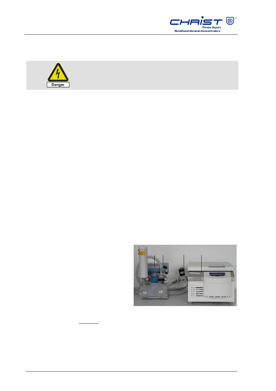
For low-boiling samples containing solvents:
1 Vacuum pump
2 Vacuum hose
3 Stop valve
4 Rotational vacuum
concentrator
Fig. 5.1: Connection of the vacuum pump
Attention: The set-up in the photo is for demonstration purposes only!
Normally, the stop valve is installed behind the rotational vacuum
concentrator and cannot be seen from the front.
The Vacuum pump must be connected to the rotational vacuum
concentrator as shown in the figure above. The connector of the stop
valve must be plugged into the socket on the back of the unit.
1 2
3
4