Directory
Brands
LINK Systems manuals
Measuring instruments
OmniLink 5000
Manual

LINK Systems OmniLink 5000 User Manual

Page 95

  • Text mode
  • Original mode
background image

7.3

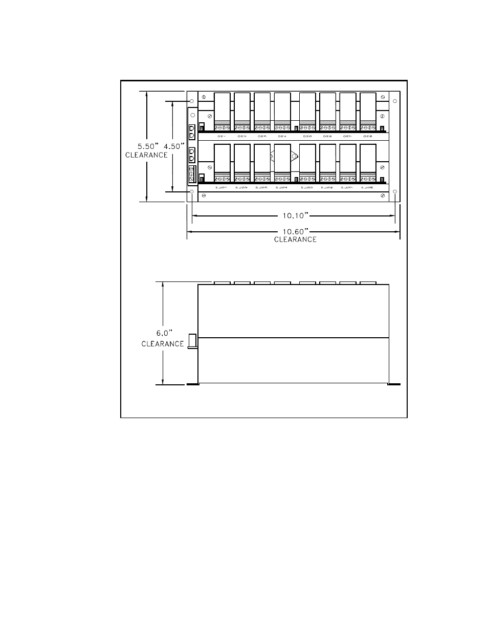
The physical layout and mounting dimensions for the relay module are shown in Figure 7.4.

Figure 7.4 Output Power Supply and Relay Modules
Dimensions

Pages: 1 … 93 94 95 96 97 … 115
  • wrong Brand
  • wrong Model
  • non readable
See also other documents in the category LINK Systems Measuring instruments:
  • Max Presence Sensing Device (48 pages)
  • LinkNet I (47 pages)
  • LinkNet II (99 pages)
  • Microlink (26 pages)
  • OmniLink 5000 (77 pages)
  • OmniLink 5000 (39 pages)
  • OmniLink 5000 (81 pages)
  • OmniLink - Feed Interface (40 pages)
  • OmniLink - PLC Interface (53 pages)
  • OmniLink II Press Automation Control (154 pages)
  • Omni II Automatic Setups Module (77 pages)
  • 5100-8 Tonnage & Analog Signal Monitor (86 pages)
  • System 1100 Tonnage Monitor (117 pages)
  • System 2500 PLS (79 pages)
Home Brands Popular manuals Recently added
Manuals Directory

© 2012–2025, azmanual.top
All rights reserved.