LINK Systems OmniLink 5000 User Manual
Page 20
4.2
6.
The status of the order and batch counter. This includes the preset limit, the present quantity
produced, and the on/off state of the counter.
7.
A bar graph which represents the current main motor speed.
8.
A bar graph which represents the current main motor load.
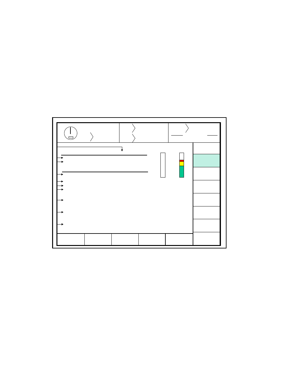
Section 4.2 Press Control Menu
Figure 4.2 shows the Press Control Menu. This screen provides detailed information about the press, the
press control, and auxiliary equipment. The softkeys shown active in the PROG mode indicate parameters
that can be changed.
Stroke
Mode Single Stroke
Drive
Speed
Stroke
Speed
SPM
SPM
0
0
Order
Counter
PC STATUS
Counter OFF
PRESS
CONTROL
CHANGE
NUMBER
MOTOR
SPEED
TONNAGE
MONITOR
AUTO
SETS
DIE
PROTECTION
EXIT
0
0
SPM
0
% LOAD
161
READY TO STROKE
TOP
AUXILIARY
COMM.
DIAGNOS
OPERATOR
STATON
Brake Monitor
Limit
Stoptime
Top Stroke Stop
0200
183
mSec
Mid Stroke Stop
0250
0
mSec
Clutch time
0275
0250
mSec
Limit
Actual
Auto Single Stroke Time ……… 5
Sec
Feed Complete Position ……… 25
Degs
Cont. on Demand Time ……….
10
Mins
Auxiliary Equipment Message
Option is not Installed
Reason for the Last Stop
Power Up
Present Running Status
Ready to Stroke
1
2
10
5
6
7
4
8
9
3
Figure 4.2 Press Control Menu
The display provides the following information:
1.
A brake monitor used when the press stops at the top of the stroke.
2.
A brake monitor used when the press stops at any position other than top.
3.
The actual stopping time of the press, measured by the brake monitor.
4.
Clutch engagement time.
5.
Auto Single Stroke Time
6.
Feed Complete Position