LINK Systems OmniLink 5000 User Manual
Page 50
5.3
Stroke
Mode Single Stroke
Drive
Speed
Stroke
Speed
SPM
SPM
200
0
Order
Counter
PC STATUS
Counter OFF
TOP STOP
CALIBRATE
CHANGE
NUMBER
0
0
Program/Run Switch
TOP
EXIT
MOTOR
SPEED
Speed Advance Top Stop
Stroking
Mode
Single
Continuous
Speed and Stopping Angle
50
340
338
100
330
328
150
320
318
200
310
308
RPM
[ Calculated }
Speed Top Ang
Measured
Stop Ang
Ch A 050 340 340
Ch B 050 340 340
Stop Pos (Setup Mode) = 090
1
2
3
4
5
6
7
8
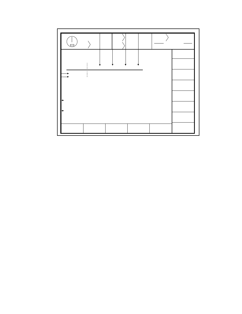
Figure 5.3 Top Stop Configuration Menu Link
Standard Firmware
The display shows the following information:
1.
The programmed lowest operating speed of the machine.
2.
The programmed speed approximately 1/3 of the way between lowest and highest programmed
speeds.
3.
The programmed speed approximately 2/3 of the way between lowest and highest programmed
speeds.
4.
The programmed highest operating speed of the machine
5.
The programmed angle at which the press will begin to stop when running at each speed shown.
These four angles are used when the press is in a single stroke mode, and will automatically stop at
the end of each stroke.
6.
The programmed angle at which the press will begin to stop when running at each speed shown.
These four angles are used when the press is in continuous running mode.
7.
The actual speed of the crankshaft and computed top stop position recorded by the press control each
time a stroke is made.
8.
The programmed angle at which the press will begin to stop in the downstroke when operated in
Setup/Stop Time Test mode. See Section 5.1.3.