LINK Systems OmniLink 5000 User Manual
Page 24
4.6
1
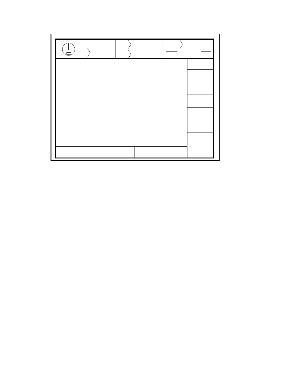
L. N.O. INCH BUTTON
LO
LO
2
R. N.O. INCH BUTTON
LO
LO
3
L. N.O. STATION # 1
LO
LO
4
R. N.O. STATION # 1
LO
LO
5
L. N.O. STATION # 2
LO
LO
6
R. N.O. STATION # 2
LO
LO
7
L. N.O. STATION # 3
LO
LO
8
R. N.O. STATION # 3
LO
LO
9
L. N.O. STATION # 4
LO
LO
10
R. N.O. STATION # 4
LO
LO
11
ALL N.C. RUN BUTTONS
HI
HI
12 T-STOP
TOP STOP
HI
HI
13 E-STOP
EMERGENCY STOP
HI
HI
14 E-STOP
EMERGENCY STOP
HI
HI
15 E-STOP
LIGHT CURTAIN 1
HI
HI
16 E-STOP
LIGHT CURTAIN 2
HI
HI
17
STATION 1 SELECT
HI
HI
18
STATION 2 SELECT
LO
LO
19
STATION 3 SELECT
LO
LO
20
STATION 4 SELECT
LO
LO
21
MODE (RUN)
HI
HI
22
MODE (MODE SELECT)
LO
LO
23
AUTOMATIC SETUP
LO
LO
24
CONTINUOUS SETUP
LO
LO
Stroke
Mode Single Stroke
Drive
Speed
Stroke
Speed
SPM
SPM
0
0
Order
Counter
PC STATUS
Counter OFF
INPUT
DIAGNOSTIC
VIEW
OUTPUTS
MEMORY
COMPARE
EVENT
LOG
EXIT
0
0
READY TO STROKE
TOP
Input Module 1
Num Type
Name
CHA
CHB
NEXT
PAGE
VERSION
INFO
Figure 4.3 Input Diagnostics
Section 4.2.9.2 Output Diagnostics
This screen functions similarly to the input diagnostics. This screen will show that status of the outputs.
These are Output Relays 1-16. The state indicates the condition of the output, where HI=Output On and
LO=Output Off. The status of the programmable limit switch outputs is shown on the programmable limit
switch screen.
Section 4.2.9.3 Press Control Memory Test
This menu compares the internal memory of both channels of the press control and displays any locations that
do not agree. If any parameter of either channel becomes corrupt, an error message is displayed and stroke
initiation is inhibited. Either error message "MEMORY CHECK FAULT" or "MEMORY COMPARE
FAULT" displayed in the press control's present running status indicates that a system parameter is corrupt,
and this diagnostic menu should be used to determine which parameter is bad. All locations indicated as bad
must be reprogrammed before the fault condition can be cleared. The memory comparison is done in groups,
and all are accessed with the NEXT GROUP softkey. The parameters programmed by the factory (Group
4 and 5) are not accessible by the user, but can viewed from this menu. The items tested are described below:
Group 1
Programmed in Press Control configuration and Auto Sets screens.
01
Stop time limit at the top of stroke
02
Stop time limit at mid-stroke
03
Automatic Single Stroke Time
04
Feed Complete Position
05
Continuous on Demand Time