LINK Systems OmniLink 5000 User Manual
Page 56
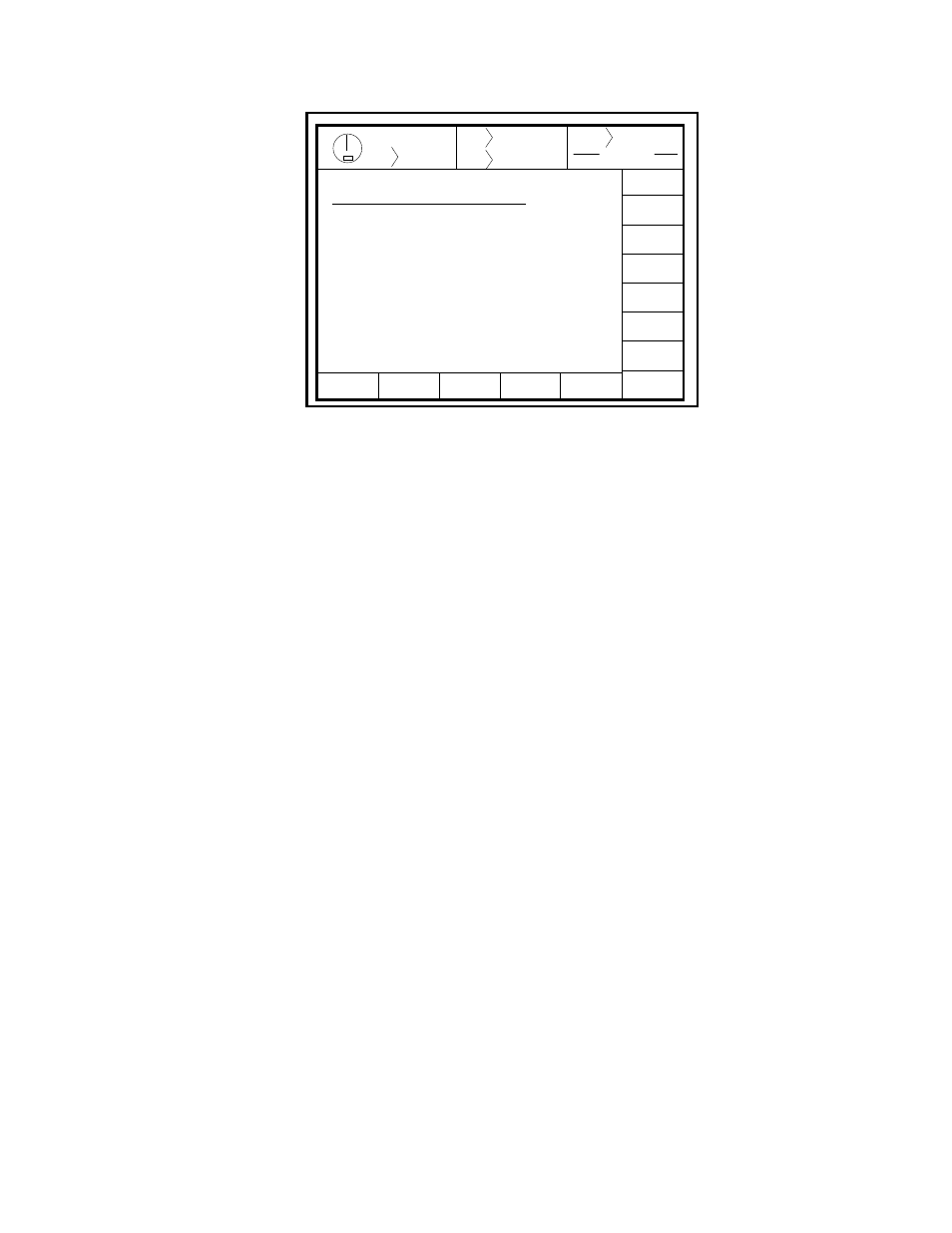
5.9
Stroke
Mode Single Stroke
Drive
Speed
Stroke
Speed
SPM
SPM
200
0
Order
Counter
PC STATUS
Counter OFF
MACHINE
PARAMETERS
CHANGE
NUMBER
0
0
Program/Run Switch
TOP
EXIT
SET
ZERO
FACTORY
CONFIG
SPEED
CONFIG
Parameter
Setting
Encoder Offset……………………..
Auto Carry Up ……………………..
Begin Timed Inch………………….
Minimum Strokes / Min …………..
Maximum Strokes / Min ………….
Motion Filter ……………………….
Clutch Engagement ……………...
Timed Inch Pulse …………………
Automatic Turn Off ……………….
Max. # Engage/Min ………………..
Top Stroke Stop Time …………….
Mid Stroke Stop Time …………….
1
180
100
50
200
1
200
50
0
0
200
240
deg
deg
deg
Spm
Spm
mS
mS
Min
mS
mS
Figure 5.5 Machine Parameters
Configuration
Section 5.2.1 Encoder Offset
The offset is to compensate for misalignment between the resolver/encoder zero and the machine zero. To
enter, the user must position the crankshaft at top dead center and press the SET ZERO softkey. The offset
value displayed is the number that must be added to the actual resolver reading to get 0°. If the present
resolver angle is within the allowable limit, the angular display value will indicate 0°. This value is limited
to ± 10° from resolver zero. If the position is beyond the limit, the limit is used as the offset. Coarse
adjustment is provided by allowing manual entry of 0°-9° or 350°-359°.
Section 5.2.2 Automatic Carry Up Position
This parameter is the angle at which the press control will automatically keep the clutch/brake valve engaged
until the machine reaches the top of the stroke. It is used only in Single Stroke and Automatic Single Stroke
modes. Once this angle is reached, an operator may release the run buttons without causing the press to stop.
This value is limited to between 120° and 180°, and an entry beyond the limit is rejected.
Section 5.2.3 Begin Timed Inch Position
This parameter is the angle in the downstroke at which the press control will enter timed inch. It is used only
if the Timed Inch mode is selected. The timed inch function will continue until the crankshaft angle reaches
180°, or another stroking mode is selected. This value is limited to between 0° and 135°, and an entry
beyond the limit is rejected.
Section 5.2.4 Minimum Strokes/Minute
This parameter is the minimum speed threshold for the motion detector. It is used to verify clutch
engagement and to detect loss of resolver/encoder motion due to a failure in mechanism (chain etc.) that
connects the resolver/encoder to the crankshaft. The threshold is used to indicate the start of motion or the
loss of motion and should therefore be set well below the actual minimum operating speed of the press. This
value is limited to between 2 and 100 rpm, and an entry beyond the limit is rejected. Entries are rounded to