Figure 5.2 configurations menu – LINK Systems OmniLink 5000 User Manual
Page 48
5.1
Section 5 Press Control Configuration Menus
The System 5000 allows the user to configure the control and the operator terminal for specific machine
requirements. This restricted menu section is accessed from the Press Control menu. The Configuration
softkey is available only in the Program/Run switch is in the PROG position. The Press Control menu with
the Program/Run switch in the PROG position is shown in Figure 5.1.
Stroke
Mode Single Stroke
Drive
Speed
Stroke
Speed
SPM
SPM
0
0
Order
Counter
PC STATUS
Counter OFF
PRESS
CONTROL
CHANGE
NUMBER
MOTOR
SPEED
TONNAGE
MONITOR
AUTO
SETS
DIE
PROTECTION
EXIT
0
0
SPM
0
% LOAD
161
Program/Run Switch
TOP
AUXILIARY
COMM.
DIAGNOS
OPERATOR
STATON
Brake Monitor
Limit
Stoptime
Top Stroke Stop
0200
183
mSec
Mid Stroke Stop
0250
0
mSec
Clutch time
0275
0250
mSec
Limit
Actual
Auto Single Stroke Time ………
5
Sec
Feed Complete Position ……… 25
Degs
Cont. on Demand Time ……….
10
Mins
Auxiliary Equipment Message
Option is not Installed
Reason for the Last Stop
Power Up
Present Running Status
Ready to Stroke
CONFIGURE
Figure: 5.1 Press control menu
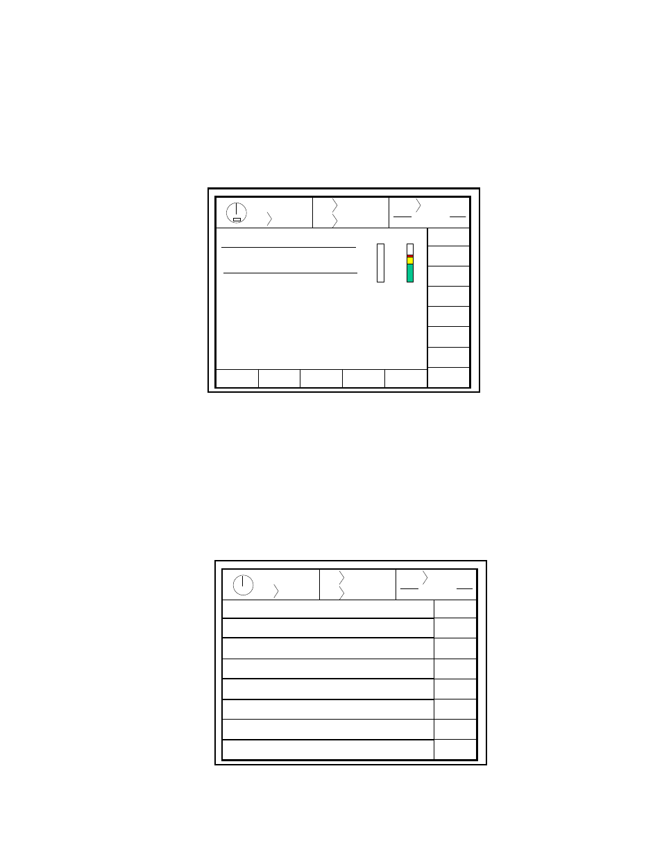
If the CONFIGURE softkey is selected, the display will ask for the Configuration code. This Configuration
code is user programmable. The original code is sent from the factory to a person so designated when the
control is ordered. See Section 9.2. The user has the option of keeping the original code or changing to
another. The user must record and protect the current code. This code must be provided to qualified
personnel only. If entered correctly, a selection of configuration menus shown in Figure 5.2 is presented.
Once access to the configuration menu has been granted, the Program/Run switch may be switched back and
forth between PROG and RUN. The configuration mode will remain in effect until manually Exited,
returning the display to the press control menu.
Stroke
Mode Single Stroke
Drive
Speed
Stroke
Speed
SPM
SPM
0
0
Order
Counter
PC STATUS
Counter OFF
P/C
CONFIG.
EXIT
0
0
Program/Run Switch
TOP
NAMES
RESTRICTED
PLS
TOP STOP
CALIBRATE
MACHINE
PARAMETERS
LUBE
OPERATOR
TERMINAL
Top Stop Calibration
Machine Parameters
Lubrication System
Operator Terminal
Restricted Programmable Limit Switch
Names and Messages
Exit Calibration
Figure 5.2 Configurations Menu