Figure 3.1 password entry sequence – LINK Systems OmniLink 5000 User Manual
Page 16
3.5
items. All restricted items are accessible when the Program/Run key switch is switched to the PROG
position.
When operating in the “Key or Password” mode, the key switch is one of the means available to access the
restricted items. All restricted items are accessible when the Program/Run key switch is switched to the
PROG position.
When operating in the “Key and Password” mode, the key switch and password must be used to access the
restricted items. In this mode, the user will be granted access only to the restricted items that have been
assigned to him.
Section 3.3.2 Password System Operation
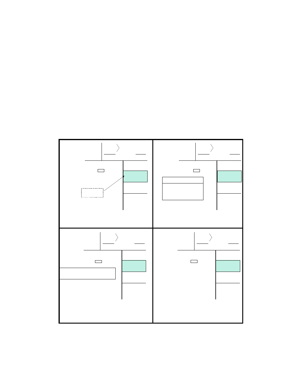
Figure 3.1 displays a typical password entry sequence. This example shows the steps necessary to change
the motor speed. This is typical for password entry for all restricted items.
SPM
SPM
0
0
Order
Counter
PC STATUS
READY TO STROKE
Counter OFF
MOTOR
SPEED
CHANGE
NUMBER
SPM
UP
SPM
DOWN
SPM
SPM
0
0
Order
Counter
PC STATUS
READY TO STROKE
Counter OFF
MOTOR
SPEED
SUPPLY
ACCESS
CODE
SPM
UP
SPM
DOWN
SPM
SPM
0
0
Order
Counter
PC STATUS
READY TO STROKE
Counter OFF
MOTOR
SPEED
CHANGE
NUMBER
SPM
UP
SPM
DOWN
SPM
SPM
0
0
Order
Counter
PC STATUS
READY TO STROKE
Counter OFF
MOTOR
SPEED
SELECT
SPM
UP
SPM
DOWN
MOTOR SPEED ……. 200 SPM
MOTOR SPEED ……. SPM
MOTOR SPEED ……. 200 SPM
MOTOR SPEED ……. 200 SPM
SELECT A USER NAME
USER NUMBER ONE
USER NUMBER TWO
USER NUMBER FIVE
USER NUMBER ONE CODE _______
STEP A: SELECTING PARAMETER TO BE CHANGED
STEP B: SELECTING USER NAME
STEP C: ENTERING USER PASSWORD
STEP D: CHANGING PARAMETER
LEGEND FOR
SOFTKEY #1
Figure 3.1 Password Entry Sequence