Bit subsystem selection input pins, Device manager user’s guide 4-7 – Echelon DM-21 Device Manager User Manual
Page 47
Device Manager User’s Guide
4-7
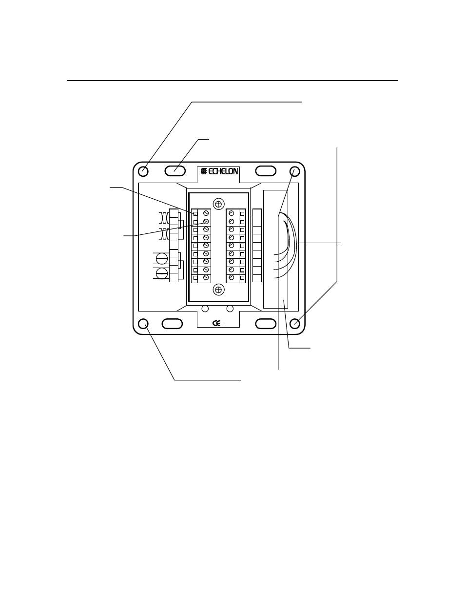
4-bit Subsystem selection Input Pins
Threaded screw holes for
attaching DM-21 to Base
Plate. Use 8-32, 3/8"
screw, Echelon 205-
0130-01 or equal.
0.180" x 0.280" hole for
attaching Base Plate to
electrical back box or sub-
panel. Use 6-32, flat-head,
3/8" minimum screw.
Wire
Entry
Terminal
Screw,
Tightening
Torque 4
lbs. in.
1 2 3 4 5 6 7 8
9
10 11 12 13 14 15 16 17 18
Model
40111
Writing Space for
Installer.Use Fine Point
Sanford Sharpie Model
30001 Or Equal.
0.230" holes for attaching
Base Plate to electrical
back box or sub-panel.
USE AT LEAST 24 AWG, 90°C RATED
WIRE
Network
16-30VAC or VDC, CLASS 2
UL
c
UL
LISTED
ENERGY MANAGMENT
EQUIPMENT SUBASSEMBLY
178K
+5VDC
GROUND
RESERVED
RESERVED
RESERVED
DB 3
DB 2
DB 1
DB 0
Net 1
Net 1
Net 2
Net 2
Shiel
d
14-30
14-30
14-30
14-30
4-bit
subsystem
selection
input
Figure 4.3 – Type 1 Base Plate, Rear Wiring Panel
The DM-20/21 supports up to 16 subsystems. The subsystem is selected by
setting a 4-bit binary input on the subsystem selection input. Subsystem selection
input pins for the DM-21 are terminals 10, 11, 12, and 13 on the Type 1/1D back-
plate, representing bits 0 to 3 respectively. Subsystem selection input pins for the
DM-20 are pins 14, 12, 9, and 10 of JP1 representing bits 0 to 3, respectively.
Tables 4.4 and 4.5 present the arrangement of jumpers to set the correct
subsystem using the 4-bit subsystem selection inputs.
If only a single database is specified by the DM Pin Usage configuration property,
the DM-20/21 will ignore the subsystem selection setting. The pins/terminals
may then float high or low.