I/o cabling, Device manager user’s guide 3-3 – Echelon DM-21 Device Manager User Manual
Page 23
Device Manager User’s Guide
3-3
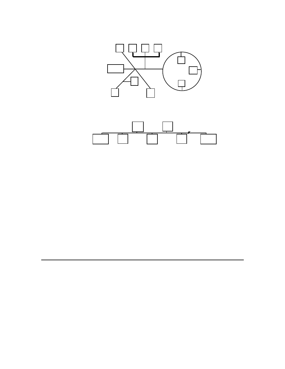
Termination
Figure 3.4 Mixed Topology (Model 44100 Terminator)
Termination
Termination
Figure 3.5 Doubly Terminated Bus Topology - Used for Very Long Cabling
Distances
(Two Model 44101 Terminators)
A network consisting of devices using the FTT-10A transceiver is said to reside on
a “TP/FT-10 channel.” In some cases all of the devices will be connected to a
single TP/FT-10 channel. A maximum of 64 devices (LonPoint modules, routers,
PCLTA-10 and PCC-10 PC adapters, third-party LONMARK
®
devices) may be
connected to any one channel. If more than 64 devices are to be used, or if it is
necessary to add more cabling than is permitted on a single channel, then one or
more model 42100 LPR-10 Routers (TP/FT-10 to TP/FT-10) would be placed in
series with the network cabling.
See the Junction Box and Wiring Guidelines for Twisted Pair L
ON
W
ORKS
Networks (engineering bulletin 005-0023-02) and the L
ON
W
ORKS
FTT-10A Free
Topology Transceiver User's Guide (078-0156-01), available at
http://www.echelon.com/products/technical/manuals.asp, for more information
about using the TP/FT-10 channel and FTT-10A transceiver.
I/O Cabling
The installer generally has wide latitude in the type of cabling selected for the
I/O. It is good practice to ensure that all cabling is made from twisted pair wire,
as this has the advantage of minimizing susceptibility to differential noise. Note
when selecting the cabling that the Base Plate screw terminals accommodate
wire gauges from 24AWG/0.5mm to 12AWG/2mm. In all cases, use at least 90°C
rated wire.