Electrical – Echelon DM-21 Device Manager User Manual
Page 43
Device Manager User’s Guide
4-3
mounted on its motherboard PCB). All measurements are to the centers of the
pins on JP1.
The DM-20 occupies a volume of 4 x 4 x 1 inches (10.2 x 10.2 x 2.5 cm), and other
components should be kept out of this volume. The four standoffs are 0.75 inches
long, and either #4 or #6 standoffs may be used. If the DM-20 assembly is
conformally coated (this requires advance approval from Echelon to avoid voiding
the product warranty) before mounting it on the motherboard, special care should
be taken to not coat the four conductive screw holes on the DM-20 PCB that
connect to the four standoffs.
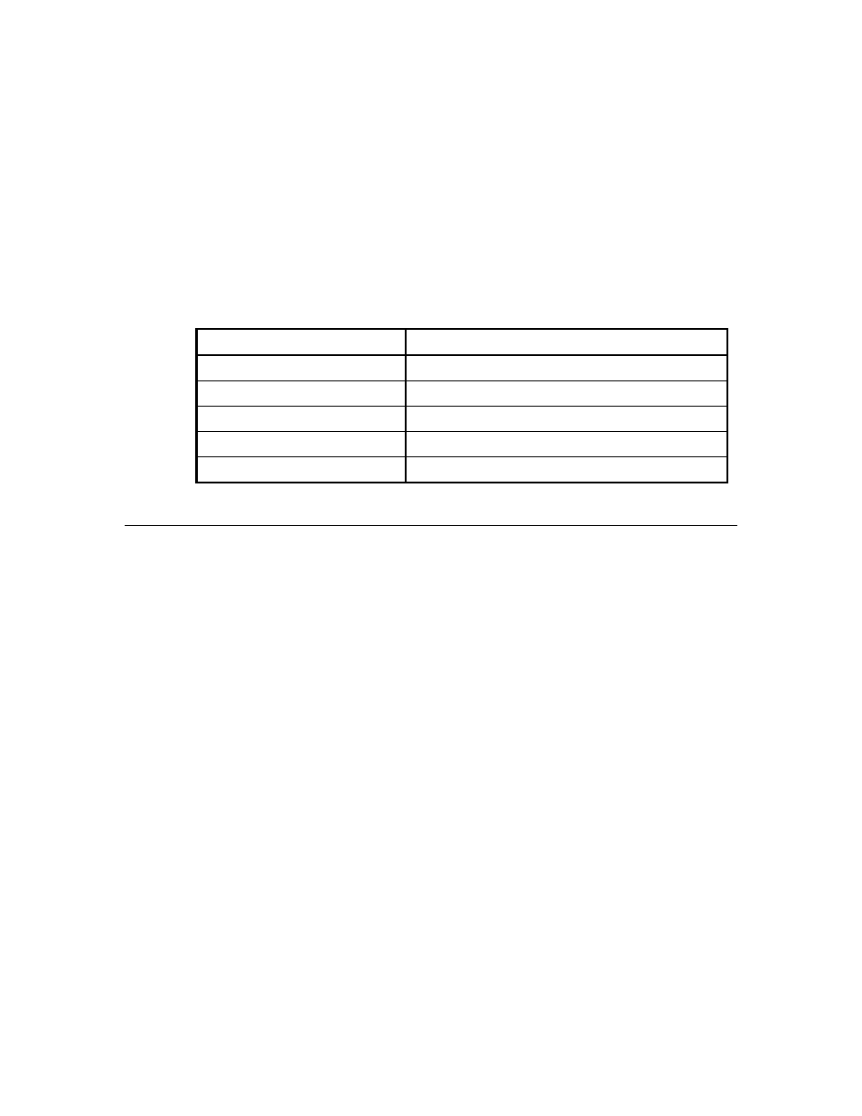
Table 4.1 – DM-20 Mechanical Interface
Mounting holes
4
Screw size for mounting holes
#4 or #6
Motherboard standoff height
0.75 inches
Module connector
2 x 7 pin, 100 mil pitch male header
Motherboard mating connector
Samtec SSW-107-01-S-D-LL, 2x7 socket strip
Approximate module size
4 x 4 x 1 inches
Electrical
The grounding provided by the standoffs is an important part of the EMC design
of the DM-20. The standoff nearest C410 is connected to the DM-20 module’s
chassis ground, and the other three standoffs are connected to the DM-20
module’s logic ground. The DM-20 module’s chassis ground standoff must be
connected via a low-impedance path to the chassis of the metal enclosure. The
DM-20 module’s logic ground standoffs should be connected to the logic ground of
the motherboard.