Pin description, Dm-21 device manger hardware interface – Echelon DM-21 Device Manager User Manual
Page 44
4-4
Device Manager Hardware Description and Installation
Pin Description
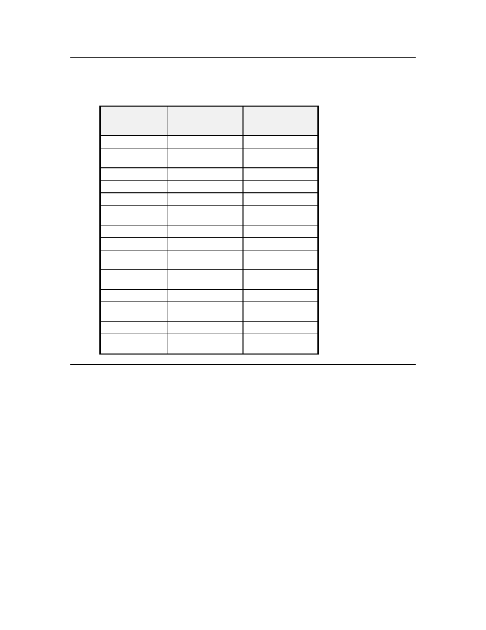
The DM-20 module has a single 2x7 connector. The pinout is described in table 5.2.
Table 4.2 DM-20 Pinout
JP1 2x7
Connector Pin
Number
DM-20 Module
Signal Type
Description
1
FTT-10A
Net1
2
+5V DC Power input
+5V±5% input @ 150
mA
3
FTT-10A
Net2
4
Ground
Ground
5
Not used
6
Neuron ~Service
Neuron Service Pin
signal
7 (Neuron IO)
Neuron IO
Reserved
8 (Neuron IO)
Neuron IO
Reserved
9 (Neuron IO)
Neuron IO
4-bit subsystem
selection input (bit 2)
10 (Neuron IO)
Neuron IO
4-bit subsystem
selection input (bit 3)
11
Do not connect
12 (Neuron IO)
Neuron IO
4-bit subsystem
selection input (bit 1)
13
Do not connect
14 (Neuron IO)
Neuron IO
4-bit subsystem
selection input (bit 0)
DM-21 Device Manger Hardware Interface
The front panel of the DM-21 module is shown in figure 4.2. A single Status LED
is provided for the device.