10 network cabling and base plate installation – Echelon DM-21 Device Manager User Manual
Page 30
3-10
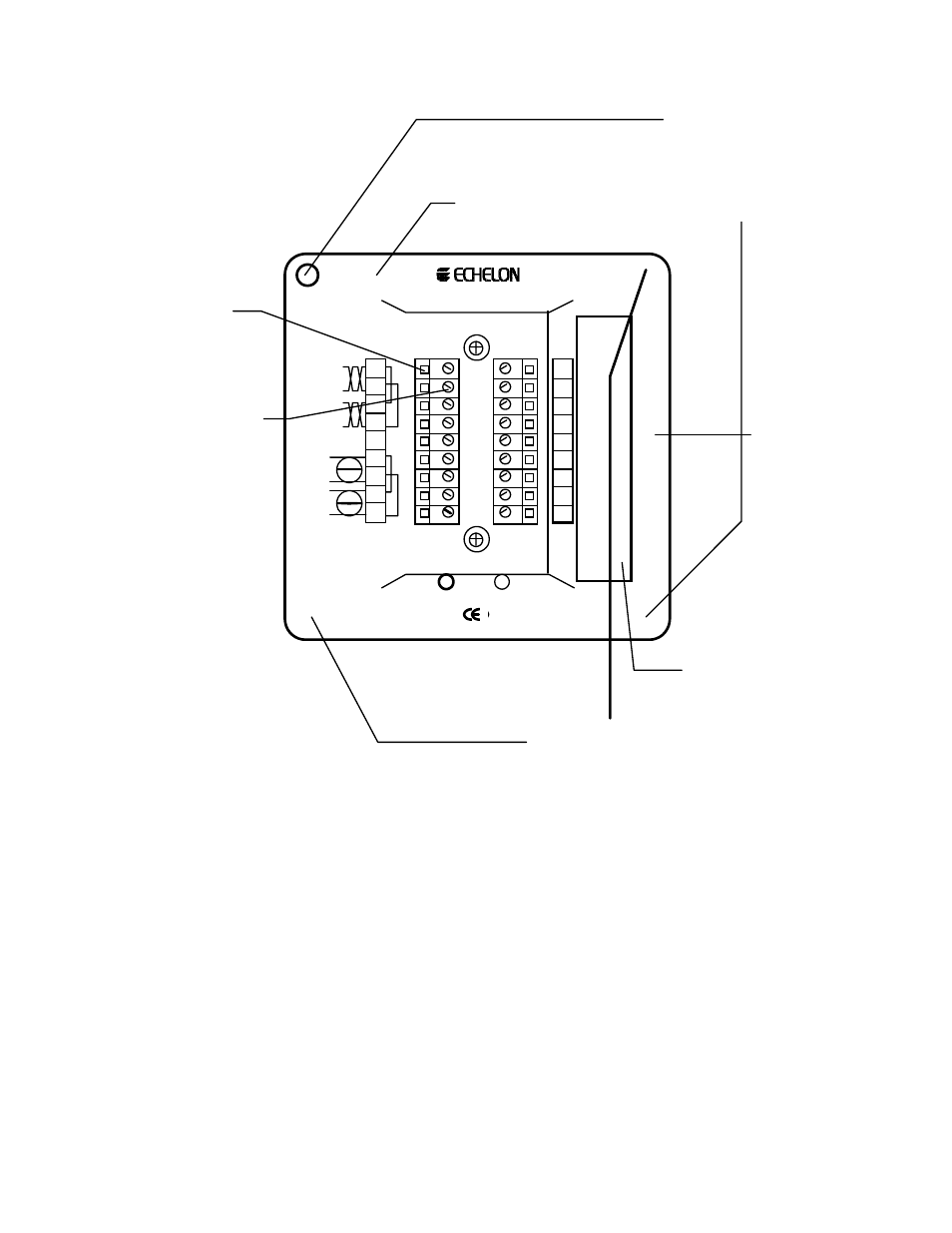
Network Cabling and Base Plate Installation
Threaded screw holes fo
attaching DM-21 to Base
Plate. Use 8-32, 3/8"
screw, Echelon 205-
0130-01 or equal.
0.180" x 0.280" hole for
attaching Base Plate to
electrical back box or sub-
panel. Use 6-32, flat-head,
3/8" minimum screw.
Wire
Entry
Terminal
Screw,
Tightening
Torque 4
lbs. in.
1 2 3 4 5 6 7 8 9
10 11 12 13 14 15 16 17 18
Model 40111
Writing Space for
Installer.Use Fine Poin
SanfordSharpie
Model
30001 Or Equal.
0.230" holes for attaching
Base Plate to electrical
back box or sub-panel.
USE AT LEAST 24 AWG, 90°C RATED WIRE
Network
16-30VAC or VDC, CLASS 2
UL
c
UL
LISTED
ENERGY MANAGMENT
EQUIPMENT SUBASSEMBLY
178K
+5VDC
GROUND
RESERVED
RESERVED
RESERVED
DB 3
DB 2
DB 1
DB 0
Net 1
Net 1
Net 2
Net 2
Shield
14-30
14-30
14-30
14-30
4-bit
subsystem
selection
input
Figure 3.9 – Type 1 Base Plate - Rear Wiring Panel