The dm-20 device manager hardware interfaces, Mechanical – Echelon DM-21 Device Manager User Manual
Page 42
4-2
Device Manager Hardware Description and Installation
The DM-20 Device Manager Hardware Interfaces
Mechanical
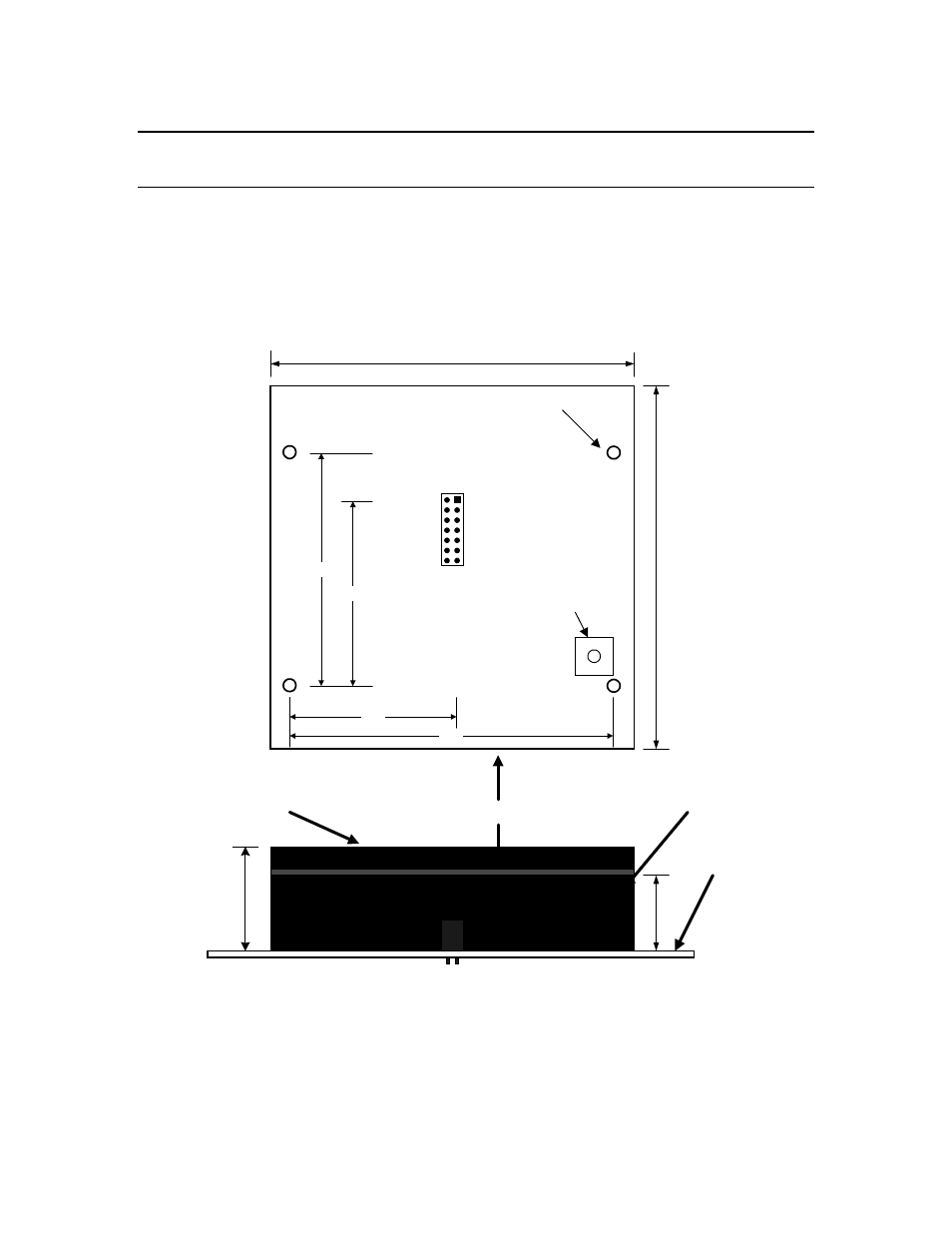
Figure 4.1 shows a DM-20 module mounted onto a motherboard PCB (all
dimensions are in inches):
2.30
1.825
3.20
1.65
1
3
5
7
9
11
13
2
4
6
8
10
12
14
4.0
4.0
0.75
1.0
Keep-Out Volume (4 x 4 x 1 inches)
DM-20 PCB
0.75 inch Standoffs (4 places)
Top View of Motherboard 2x7 Connector
and Standoff Positions (as seen looking down on the DM-
20 when mounted on its Motherboard)
Side View of DM-20 PCB Mounted
Onto Motherboard With Standoffs
Motherboard
Chassis Ground
Service Switch
Figure 4.1 - DM-20 PCB Mounted onto Motherboard
The positions of the standoffs and 2x7 motherboard connector are shown in the
top portion of the previous figure (as seen when looking down on the DM-20 when