Dm-21 pinout – Echelon DM-21 Device Manager User Manual
Page 46
4-6
Device Manager Hardware Description and Installation
DM-21 Pinout
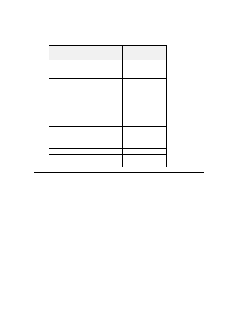
Table 4.3 – DM-21 Pinout
Rear Panel Pin
Number (DM-21
only)
DM-21
Signal Type
Description
1 & 3
FTT-10A
Net 1
2 & 4
FTT-10A
Net 2
5
No Connect
6 & 8
16 - 30 VAC or DC
Power input
16 – 30 VAC or DC power
@ 2.4VA
7 & 9
16 - 30 VAC or DC
Power input
16 – 30 VAC or DC power
@ 2.4VA
10
Neuron IO
4-bit subsystem selection
input (bit 0)
11
Neuron IO
4-bit subsystem selection
input (bit 1)
12
Neuron IO
4-bit subsystem selection
input (bit 2)
13
Neuron IO
4 bit subsystem selection
input (bit 3)
14
Neuron IO
Reserved
15
Neuron IO
Reserved
16
Neuron ~Service
Neuron Service Pin
17
Ground
Ground
18
+5V DC Power outpu
+5V+/- 5% output @ 20mA
This manual is related to the following products: