Device manager user’s guide 3-13, Figure 3.12 - front side of type 1d din base plate – Echelon DM-21 Device Manager User Manual
Page 33
Device Manager User’s Guide
3-13
Network
CAUTION
18
17
16
15
14
13
12
11
10
1
2
3
4
5
6
7
8
9
I/O
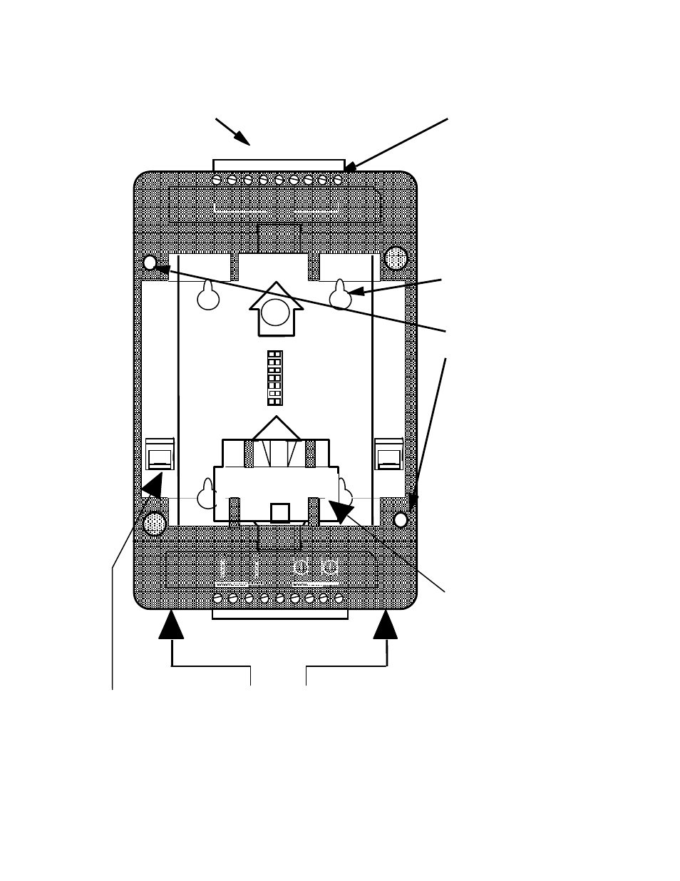
Threaded screw holes for
attaching LonPoint
modules to the Base Plate.
Use 8-32, 3/8" screw,
Echelon 205-0130-01 or
equal
Terminal screw,
tightening torque 4lbs.
in. (0.5Nm) maximum
Wire entry
Jumper Plug
storage location -
remove before
installing DM-21.
Jumper Plug
insertion
points
Keyhole slot for wall
or panel mounting
DIN rail release -
activate with
flathead
1A
18
17
16
15
13
12
11 10
14
1
2
3
4
6
7
8
9
5
Figure 3.12 - Front Side of Type 1D DIN Base Plate
This manual is related to the following products: