Ba.i), 10 -i – Carrier 48SX024-048 User Manual
Page 9
Attention! The text in this document has been recognized automatically. To view the original document, you can use the "Original mode".
o 15/16=^
1 9/16'
(23.8)„
(39.7)^
B
S2 49 g/16'
(1320.8) (1259.3)
OPTIONAL RETURN
AIR OPENING
13/16'
(46 2)
OPTIONAL SUPPLY
AIR OPENING
RIGHT SIDE VIEW
ACCESS PANEL
1
\ / 4
C31.75)
ALTERNATE POWER ENTRY
EVAP COIL ACCESS
0 7/0
(22.23)\
ALTERNATE LV ENTRY
_-3
5/16'
'^(BA.I)
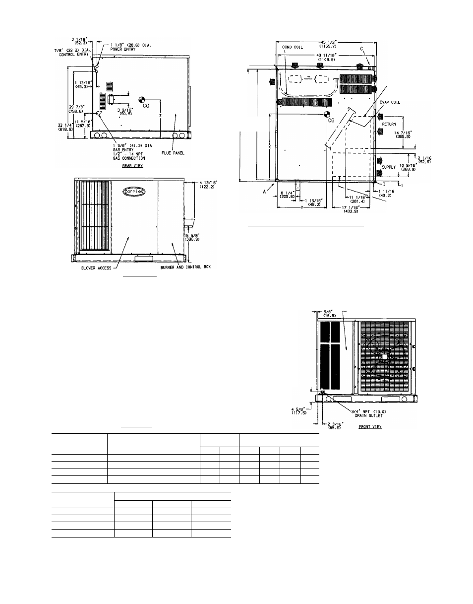
REQ’D CLEARANCES FOR SERVICING in. (mm)
Duct panel .
.
...
.
. 0
Unit top
. .
36(914)
Side opposite ducts
...
36(914)
Compressor access
36(914)
(Except for NEC requirements)
REQ’D CLEARANCES TO COMBUSTIBLE MATL. in (mm)
~
4Í7l219)
14 (356)
........................0
. . 9 (229)
. . 0
. .
30 (762)
10 1/16
(450 0)
5 5/0
(142.9)t
1 3/16-
(20
6
)
— 10 -I
(253.0)
-11 1/21
(292.1)
13 1/2'
(342.9)
11 'S/16'
■ (207.31.4
f
12 13/16'.
LEFT SIDE VIEW
1 3/8'-
(34.9)
CG
COND
LV
MAT’L
NEC
REQ’D
Maximum extension of overhangs
Unit top.......................
Duct side of unit .
Side opposite ducts
Bottom of unit
Flue panel
LEGEND
— Center of Gravity
— Condenser
— Low Voltage
— Material
— National Electrical Code
— Required
COMPRESSOR ACCESS PANEL
37 7/16"
(950 9)
UNIT
ELECTRICAL
CHARACTERI8TIC8
UNIT WEIGHT
CORNER WEIGHT
(Ib/kg)
lb
kg
A
B
C
D
488X042060,080
208/230-1-60, 208/230-3-60, 460-3-60
415
189
106/48
97/44
126/57 86/39
488X042100,120
208/230-1-60, 208/230-3-60, 460-3-60
427
194
109/50 100/45 129/59 89/40
488X048080
208/230-1-60, 208/230-3-60, 460-3-60
446
293
115/52
91/41
164/75 76/35
488X048100/120/140
208/230-1-60, 208/230-3-60, 460-3-60
458
208
118/54
94/43
167/76 79/36
W
UNIT
CENTER OF GRAVITY (in./mm)
X
Y
Z
488X042060,080
26.55/674 4
21 22/539 0
17 66/448.6
488X042100,120
26.50/673.0
21.24/539.6
17.66/448.6
48SX048080
28.25/717 6
20 04/509 0
17.66/448.6
488X048100/120/140
28.16/715.3
20 08/510 0
17.66/448 6
NOTE: Ciearances must be maintained to prevent recirculation of
air from outdoor-fan discharge
NEC REQ’D CLEARANCES, in (mm)
Between units, control box side
Unit and ungrounded surfaces, control box side
Unit and block or concrete walls and other grounded
surfaces, control box side
42 (1067)
36 (914)
42 (1067)
Fig. 9 — 488X042,048 With Optional Base Rail, Unit Dimensions