Leu)_____i~i_ sy£pu(_ 1 £.otær__ 'fì, Qf^-aw-vel – Carrier 48SX024-048 User Manual
Page 25
Attention! The text in this document has been recognized automatically. To view the original document, you can use the "Original mode".
MAXIMUM WIRE
SIZE 2 AWG
^lEU)_____i~i_
Sy£PU(_
1 £.OtÆR__ 'fì_
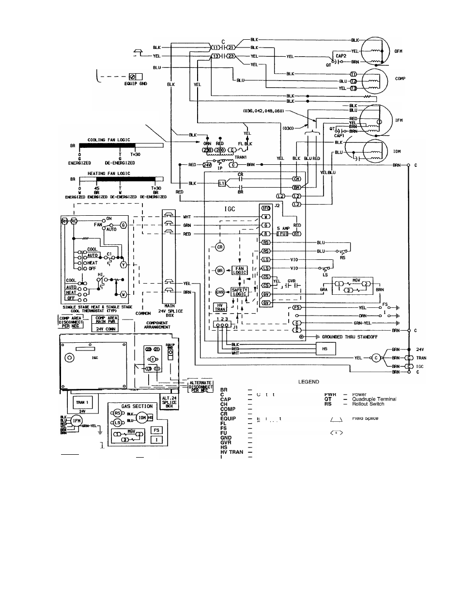
230 VOLT OPERATION AS SHOWN. FOR 208
VOLT OPERATION REVERSE RED AM) ORN
LEADS ON TRANSFORMER.
GRN-YEL—
CH C036 i 042 ONLY)
GRN-YEL---- 1|>
^QF^-aW-VEL-
COWHESSOl
CEB
CAP l(oiaT^ CAP 2( oqt ^ Blower Relay Contactor Combustion Relay Gas Valve Relay High-Voltage Transformer Ignitor Integrated Gas Control Limit Switch Main Gas Valve Terminal (Marked) Terminal (Unmarked) Splice Splice (Marked) Factory Wiring To Indicate Common Potential NOTES: 1 If any of the original wire furnished must be replaced, it must be replaced with type 90 C wire or its equivalent 2 Thermostat: HH07AT174, HH01AD040, HH01AD046 Subbase: HH93AZ040, HH93AZ176 3 Use copper conductors only Fig. 26 — 208/230-3-60 Wiring Diagram, Units 48SS030-060 25
Capacitor
Crankcase Heater
Compressor Motor
Equipment
Fuse Link
Flame Sensor
Fuse
Ground
Hall Effect Sensor
Induced-Draft Motor
Indoor-Fan Motor
Internal Protector
Field Control Wiring
Field Power Wiring
Accessory or Optional Wiring
Only, Not to Represent Wiring