Brn-vo' 1, Cap 2 (®(d(d^ cap i(oat – Carrier 48SX024-048 User Manual
Page 27
Attention! The text in this document has been recognized automatically. To view the original document, you can use the "Original mode".
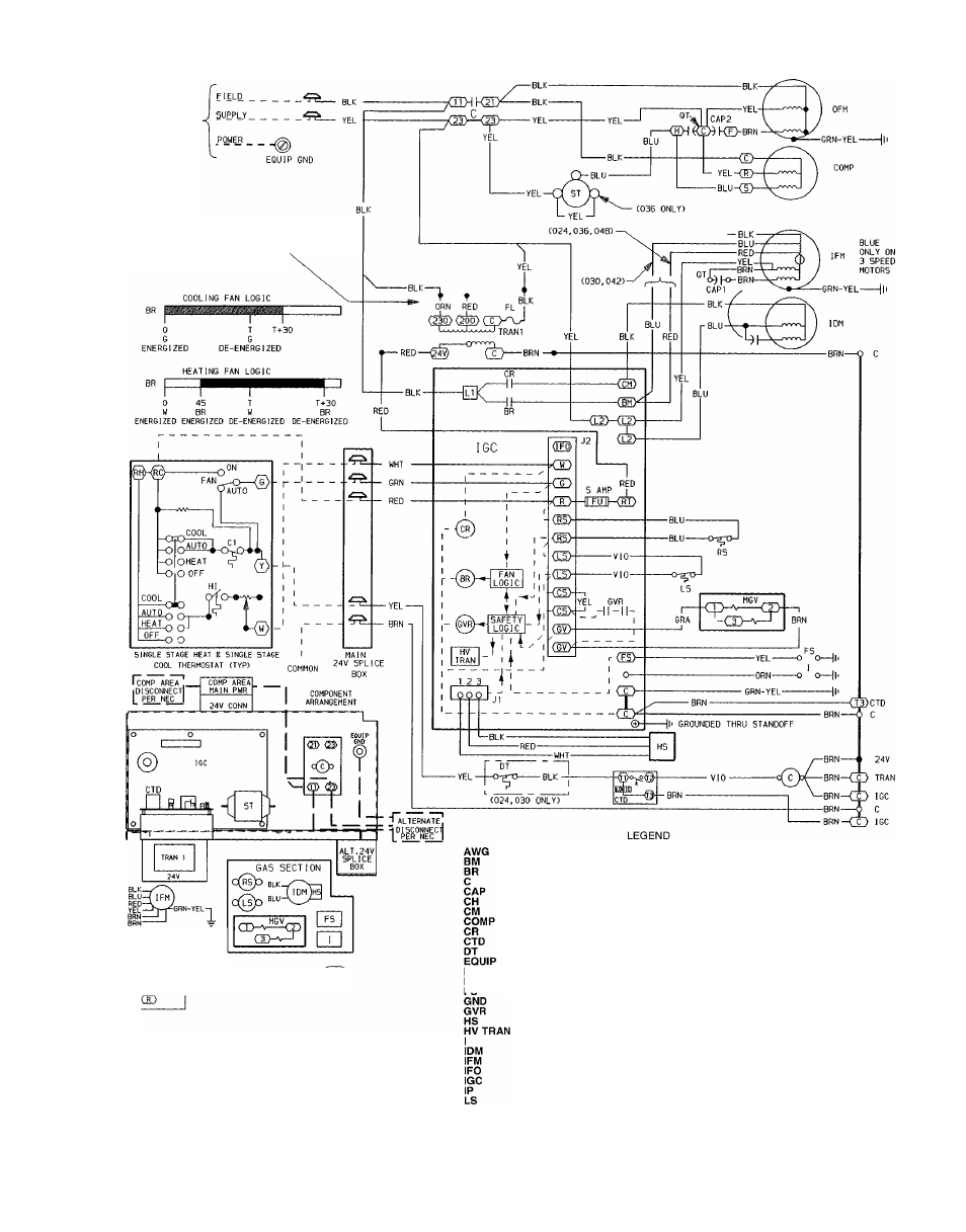
MAXIMUM WIRE
SIZE 2 AWG
230 VOLT OPERATION AS SHOWN FOR 208
VOLT OPERATION REVERSE RED AND ORN
LEADS ON TRANSFORMER
YEL—( 0FM)-6ftN-YELn
BRN-VO' 1
COMPRESSOR
CAP 2 (®(D(D^ CAP i(oaT^
NOTES:
1. If any of the original wire furnished must be replaced, it must be
replaced with type 90 C wire or its equivalent.
2 Thermostat: HH07AT174, HH01AD040, HH01AD046 Sub
base: HH93AZ040, HH93AZ176
3. Use copper conductors only.
American Wire Gage
Blower Motor
Blower Relay
Contactor
Capacitor
Crankcase Heater
Combustion Motor
Compressor Motor
Combustion Relay
Compressor Time Delay
Discharge Thermostat
Equipment
Fuse Link
Flame Sensor
Fuse
Ground
Gas Valve Relay
Hall Effect Sensor
High-Voltage Transformer
Ignitor
Induced-Draft Motor
Indoor-Fan Motor
Indoor-Fan On
Integrated Gas Control
Internal Protector
Limit Switch
Main Gas Valve
National Electrical Code
Outdoor-Fan Motor
Power
Quadruple Terminal
Rollout Switch
Start Thermistor
Transformer
Field Splice
Terminal (Marked)
Terminal (Unmarked)
Splice
Splice (Marked)
Factory Wiring
Field Control Wiring
Field Power Wiring
Accessory or Optional Wiring
To Indicate Common Potential
Only, Not to Represent Wiring
Fig. 28 - 208/230-1-60 Wiring Diagram, Units 48SX024-048
27