A caution, A warning – Carrier 48SX024-048 User Manual
Page 16
Attention! The text in this document has been recognized automatically. To view the original document, you can use the "Original mode".
(Text continued from page 13)
A
CAUTION
Unstable operation may occur when the gas valve
and manifold assembly are forced out of position
while connecting improperly-routed rigid gas pip
ing to the gas valve. Use a backup wrench when
making connection to avoid strain on, or distortion
of, the gas control piping.
A
CAUTION
If a flexible conductor is required or allowed by the
authority having jurisdiction, black iron pipe shall
be installed at the gas valve and shall extend a min
imum of 2 in. outside the unit casing.
A
WARNING
Never use a match or other open flame when check
ing for gas leaks. Never purge gas line into com
bustion chamber. Failure to follow this warning could
result in an explosion causing personal injury or death.
8. Check for gas leaks at the field-installed and factory-
installed gas lines after all piping connections have been
completed. Use soap-and-water solution (or method spec
ified by local codes and/or regulations).
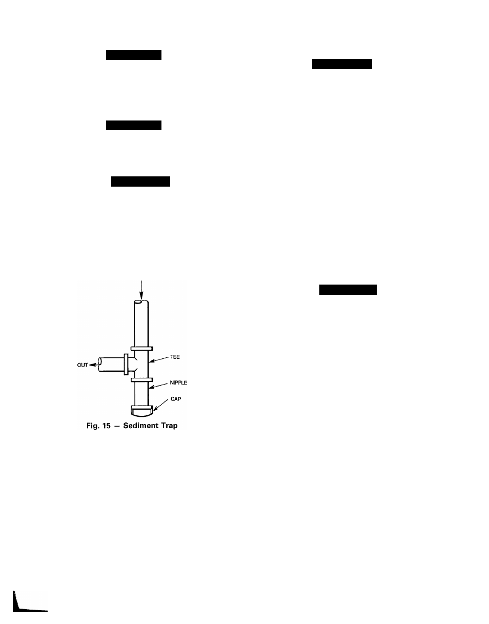
IN
Step 9 — Install Duct Connections
— The unit
has duct flanges on the supply- and return-air openings on
the side and bottom of the unit. See Fig. 2-9 for connection
sizes and locations.
CONFIGURING UNITS FOR DOWNFLOW (VERTICAL)
DISCHARGE
A
WARNING
Before performing service or maintenance operations
on the system, turn off main power to unit or electrical
shock could result.
1. Open all electrical disconnects before starting any serv
ice work.
2. Remove return duct cover located on duct panel.
Figure 16 shows duct cover removed. Save duct cover
and screws.
3. Locate lances in basepan insulation that are placed
over the perimeter of the vertical duct opening cover
(Fig. 17).
4.
Using a straight edge and shop knife, cut and
remove the insulation around the perimeter of the cover.
Remove and save 5 screws securing the cover to the
basepan and slide out the cover. Discard the cover
(Fig. 18).
5 Remove supply duct cover located on duct panel.
Figure 16 shows duct cover removed. Save duct cover
and screws.
6. Remove and discard 2 screws which secure vertical dis
charge opening cover to basepan (Fig. 19). Slide cover
forward to disengage, then tilt and remove cover through
vertical discharge opening in bottom of unit. Discard
duct cover (Fig. 20).
A
CAUTION
Collect ALL screws that were removed. Do not
leave screws on rooftop as permanent damage to
the roof may occur.
7. If unit ductwork is to be attached to vertical opening
flanges on the unit basepan (jackstand applications only),
do so at this time.
8. It is recommended that the basepan insulation around
the perimeter of the vertical return-air opening be se
cured to the basepan with aluminum tape. Applicable
local codes may require aluminum tape to prevent ex
posed fiberglass.
Cover both horizontal duct openings with the duct cov
ers from Steps 2 and 5. Make sure opening is air- and
watertight.
After completing unit conversion, perform all safety
checks and power up unit.
NOTE: The design and installation of the duct system must
be in accordance with the standards of the NFPA for instal
lation of nonresidence-type air conditioning and ventilating
systems, NFPA 90A or residence-type, NFPA 90B; and/or
local codes and residence-type, NFPA 90B; and/or local codes
and ordinances.
9.
10
i
16