Start up heating section and make adjustments, A caution, Table 5 — rated gas inputs at – Carrier 48SX024-048 User Manual
Page 22: Indicated manifold pressures, Caution
Attention! The text in this document has been recognized automatically. To view the original document, you can use the "Original mode".
Start Up Heating Section and Make
Adjustments
A
CAUTION
Complete the required procedures given in Pre-Start-Up
section above before starting the unit.
A
CAUTION
These units are designed to consume the rated gas in
puts using the fixed orifices at specified manifold pres
sures as shown in Table 5. DO NOT REDRILL THE
ORIEICES UNDER ANY CIRCUMSTANCES.
Do not jumper any safety devices when operating the unit.
Make sure that burner orifices are properly aligned. Un
stable operation may occur when the burner orifices in the
manifold are misaligned.
Follow the lighting instructions on the heating section
operation label (located inside the burner or blower access
door) to start the heating section.
NOTE; Make sure that gas supply has been purged, and
that all gas piping has been checked for leaks.
CHECK HEATING CONTROL - Start and check the unit
for proper heating control operation as follows: (See fur
nace lighting instructions located inside burner or blower
access panel.)
1. Place the room thermostat SYSTEM switch in the HEAT
position and the fan switch in the AUTO, position.
2. Set the heating temperature control of the thermostat above
room temperature.
3. The induced-draft motor will start.
4. After a call for heating, the main burner should light
within 5 seconds. If the burners do not light, there is a
22-second delay before another 5-second try. If the burn
ers still do not light, this sequence is repeated. If the
burners do not light within 15 minutes from the initial
call for heat, there is a lockout. To reset the control,
break the 24-v power to W.
5. The evaporator fan will turn on 45 seconds after the flame
has been established. The evaporator fan will turn off
45 seconds after the thermostat has been satisfied.
CHECK GAS INPUT — Check gas input and manifold pres
sure after unit start-up. (See Table 5.) If adjustment is
required proceed as follows.
The rated gas inputs shown in Table 5 are for al
titudes from sea level to 2000 ft above sea level. These in
puts are based on natural gas with a heating value of
1050 Btu/ft^ at 0.65 specific gravity, or propane gas with
a heating value of 2500 Btu/ft^ at 1.5 specific gravity.
For elevations above 2000 ft, reduce input 4% for each
1000 ft above sea level. When the gas supply being used
has a different heating value or specific gravity, refer to na
tional and local codes, or contact your distributor to deter
mine the required orifice size.
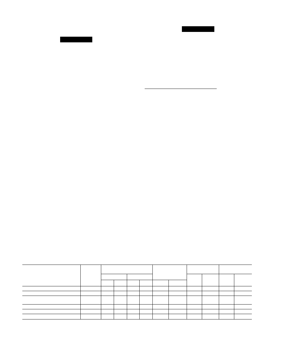
Table 5 — Rated Gas Inputs at
ADJUST GAS INPUT — The gas input to the unit is
determined by measuring the gas flow at the meter or by
measuring the manifold pressure. Measuring the gas flow
at the meter is recommended for natural gas units. The man
ifold pressure must be measured to determine the input of
propane gas units.
Measure Gas Flow (Natural Gas Units) — Minor adjust
ment to the gas flow can be made by changing the man
ifold pressure. The manifold pressure must be maintained
between 3.4 and 3.6 in. wg. If larger adjustments are
required, change main burner orifices following the rec
ommendations of national and local codes.
NOTE: All other appliances that use the same meter must
be turned off when gas flow is measured at the meter.
Proceed as follows:
1. Turn off gas supply to unit.
2. Remove pipe plug on manifold (see Fig. 23), then con
nect manometer at this point. Turn on gas to unit.
3. Record number of seconds for gas meter test dial to make
one revolution.
4 Divide number of seconds in Step 3 into 3600 (number
of seconds in one hour).
5. Multiply result of Step 4 by the number of cu ft shown
for one revolution of test dial to obtain cu ft of gas flow
per hour.
6. Multiply result of Step 5 by Btu heating value of gas to
obtain total measured input in Btuh. Compare this value
with heating input shown in Table 5. (Consult the local
gas supplier if the heating value of gas is not known.)
EXAMPLE: Assume that the size of test dial is 1 cu ft, one
revolution takes 30 seconds, and the heating value of the
gas is 1050 Btu/ft^. Proceed as follows:
1. 30 seconds to complete one revolution.
2. 3600 ^ 30 = 120.
3. 120 X 1 = 120 ft^ of gas flow/hr.
4. 120 X 1050 = 126,000 Btuh input.
If the desired gas input is 120,000 Btuh, only a minor
change in the manifold pressure is required.
Indicated Manifold Pressures
UNIT 48SS,SX
NUMBER
OF
ORIFICES
GAS SUPPLY PRESSURE
(in. wg)
MANIFOLD
PRESSURE
(in. wg)
NATURAL GAS
PROPANE*
Natural
Propane
Orifice
Drill
Size
Heating
Input
(Btuh)t
Orifice
Drill
Size
Heating
Input
(Btuh)t
Min
Max
Min
Max
Natural
Propane
018040, 024040, 030040
1
4.0
13.0
4.0
13.0
3.5
3.5
32
40,000
41
40,000
024060, 030060, 036060, 042060
2
4.0
130
40
13.0
3.5
3.5
38
60,000
46
60,000
030080, 036080, 042080,
048080, 060080
2
4.0
13.0
40
130
3.5
35
32
80,000
42
80,000
036100, 042100, 048100, 060100
3
4.0
13.0
40
13.0
3.5
3.5
36
100,000
44
100,000
036120, 042120, 048120, 060120
3
4.0
13.0
40
130
3.5
3.5
32
120,000
42
120,000
048140, 060140
3
40
130
4.0
130
35
3.5
30
136,000
40
136,000
1
S(
I
NC
When a unit is converted to propane, different size orifices must be used. See separate natural-to-
propane conversion kit instructions.
tBased on aititudes from sea ievei to 2000 ft above sea ievei. For aititudes above 2000 ft, reduce input
rating 4% for each 1000 ft above sea ievei. In Canada, from 2000 ft above sea level to 4500 ft above
sea level, derate the unit 10%.
NOTE: Unit sizes 018 and 060 are 48SS only.
22