Fig. 32 — burner access panel – Carrier 48SX024-048 User Manual
Page 42
Attention! The text in this document has been recognized automatically. To view the original document, you can use the "Original mode".
Flue Gas Passageways
— To inspect the flue col
lector box and upper areas of the heat exchanger:
1. Remove the combustion blower wheel and motor assem
bly according to directions in Combustion-Air Blower
section below.
2. Remove the 3 screws holding the blower housing to the
flue collector box cover (see Fig. 31).
3. Remove the 12 screws holding the flue collector box
cover (Fig. 31) to the heat exchanger assembly. Inspect
the heat exchangers.
4. Clean all surfaces as required using the wire brush.
BURNER
RACK
MOUNTING
SCREW
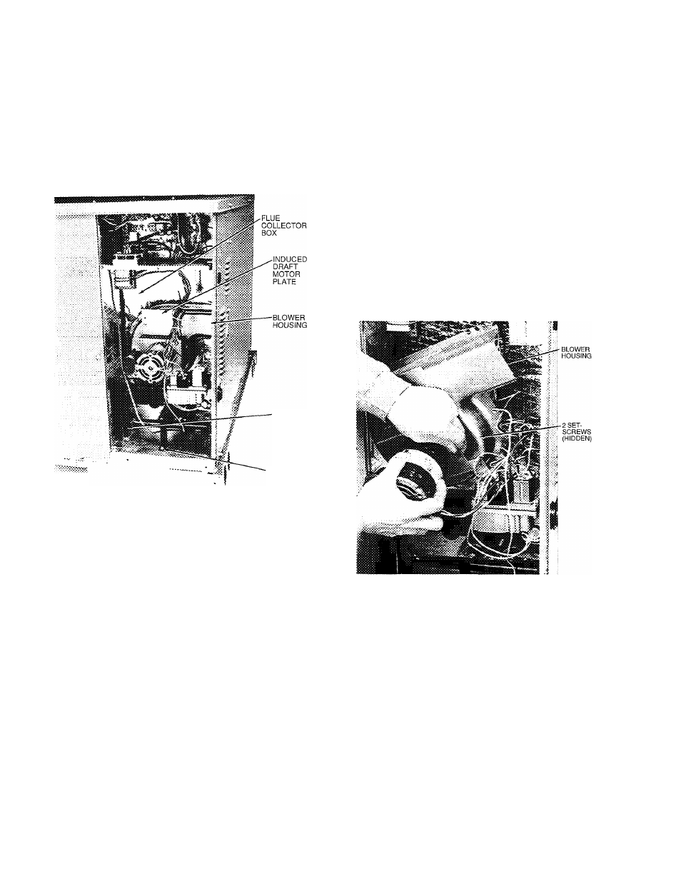
Fig. 31 — Blower Housing and Flue Collector Box
Combustion-Air Blower
— Clean periodically to as
sure proper airflow and heating efficiency. Inspect blower
wheel every fall and periodically during heating season. For
the first heating season, inspect blower wheel bimonthly to
determine proper cleaning frequency.
To inspect blower wheel, remove draft hood assembly.
Shine a flashlight into opening to inspect wheel. If cleaning
is required, remove motor and wheel as follows;
1. Remove burner access panel. (See Fig. 32.)
2. Remove the 7 screws that attach induced-draft motor mount
ing plate to blower housing. (See Fig. 31.)
3. Slide the motor and blower wheel assembly out of the
blower housing. (See Fig. 33.) Clean the blower wheel.
If additional cleaning is required, continue with Steps 4
and 5.
4. To remove blower, remove 2 setscrews. (See Fig. 33.)
5. To remove motor, remove 4 screws that hold blower
housing to mounting plate. Remove the motor cooling
fan by removing one setscrew. Remove nuts that hold
motor to mounting plate
6. To reinstall, reverse the procedure outlined above.
BURNER
-ACCESS
PANEL
t
:
Fig. 32 — Burner Access Panel
Fig. 33 — Removal of Motor and Blower Wheel
Limit Switch
— Remove blower panel. Limit switch is
located on the gas partition.
Burner Ignition
— Unit is equipped with a direct spark
ignition 100% lockout system. Ignition module is lo
cated in the control box. Module contains a self-diagnostic
LED. During servicing, refer to label diagram for LED
interpretation.
If lockout occurs, unit may be reset by either momen
tarily interrupting power supply to unit, or turning selector
switch to OFF position at the thermostat.
Main Burners
— At the beginning of each heating sea
son, inspect for deterioration or blockage due to corrosion
or other causes. Observe the main burner flames and adjust
if necessary.
t
42